
C-semi with minimum hydrodynamic forces

a technology of hydrodynamic forces and semi-submersible platforms, which is applied in the direction of special-purpose vessels, vessel construction, transportation and packaging, etc., can solve the problems of inability to support steel catenary risers, inability to use conventional semi-submersible hulls for dry tree production applications, and fatigue of steel catenary risers, etc., to reduce costs and risks, improve hull, mooring and riser system performance, and minimize the effect of wav

Active Publication Date: 2013-12-05
AKER SOLUTIONS AS
View PDF5 Cites 8 Cited by
  • Summary
  • Abstract
  • Description
  • Claims
  • Application Information

AI Technical Summary

Benefits of technology

This patent describes a new type of semiconductor material that has several advantages. It reduces the movement and forces caused by waves, electric current, and vortexes, which improves the performance of the hull, mooring, and riser system. This material also decreases costs and risks in offshore oil and gas field development.

Problems solved by technology

A conventional semi-submersible hull is unable to support steel catenary risers in extreme weather conditions.
These steel catenary risers also have fatigue problems in long term operating conditions.
Furthermore, a conventional semi-submersible hull is unable to be used for dry tree production applications while undergoing these motions.
However, these deep draft variants are still operationally limited.
EDP structures are difficult to manufacture and maintain because they use complex, large moving components.
A structure that has prolonged exposure to VIV can experience fatigue damage to components and is subject to structural failure.
However, at the same draft, the dual column semi-submersible hull only marginally improves the motions of a conventional semi-submersible hull.
In addition, the dual columns complicate design, fabrication and operation.
However, the vertical wave force on the central pontoon not substantially cancelled by the forces on the columns.
This arrangement has adverse effects, and can result in worse vertical motions than a conventional semi-submersible hull at the same draft.
The substantially deep draft required makes it cannot integrate topsides at quaysides because of water depth limitations.
The nonlinear shape and variant cross section of columns also increases fabrication complexity.

Method used


Image

  • C-semi with minimum hydrodynamic forces
  • C-semi with minimum hydrodynamic forces
  • C-semi with minimum hydrodynamic forces

Examples


Embodiment Construction

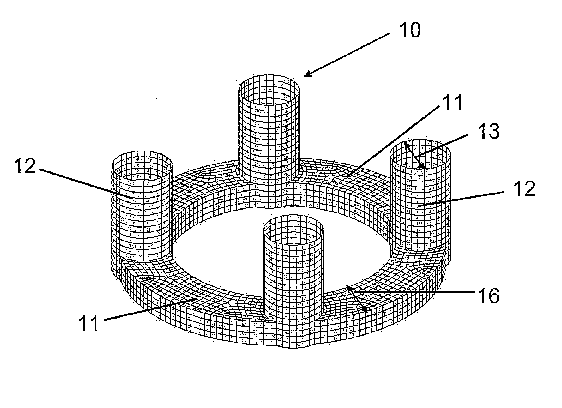
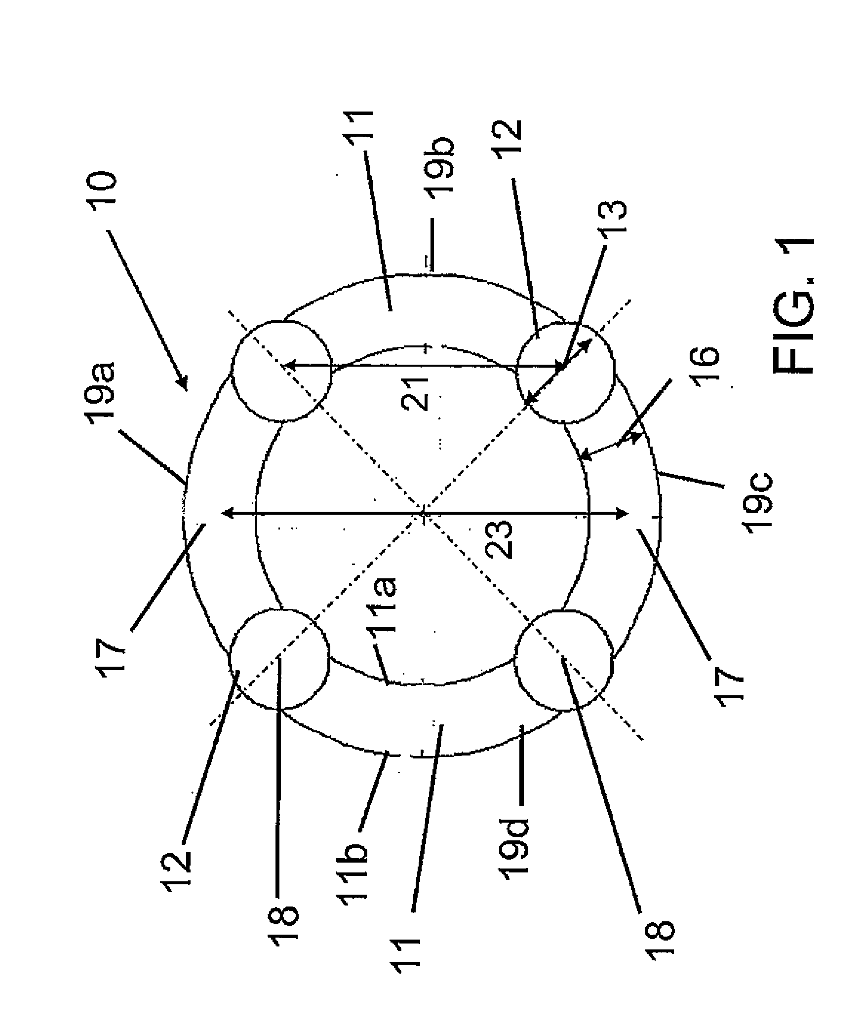
[0037]FIG. 1 is a plan view of a C-semi 10 with a circular cylindrical pontoon 11 according to an embodiment of the present invention. As shown, the four circular cylindrical columns 12 are coupled to the pontoon 11 at points along the perimeter of the pontoon 11 equidistant from each other. While the pontoon 11 may be a single structure or several separate structures, for ease in description, the pontoon 11 will be referred to as having four sections or quadrants 19a, 19b, 19c and 19d; each section is coupled to and positioned between two adjacent columns 12. The pontoon 11 is a circular, hollow toroid with an interior edge 11a and an exterior edge 11b. The pontoon can be filled with buoyant material such as air, or ballast such as water.

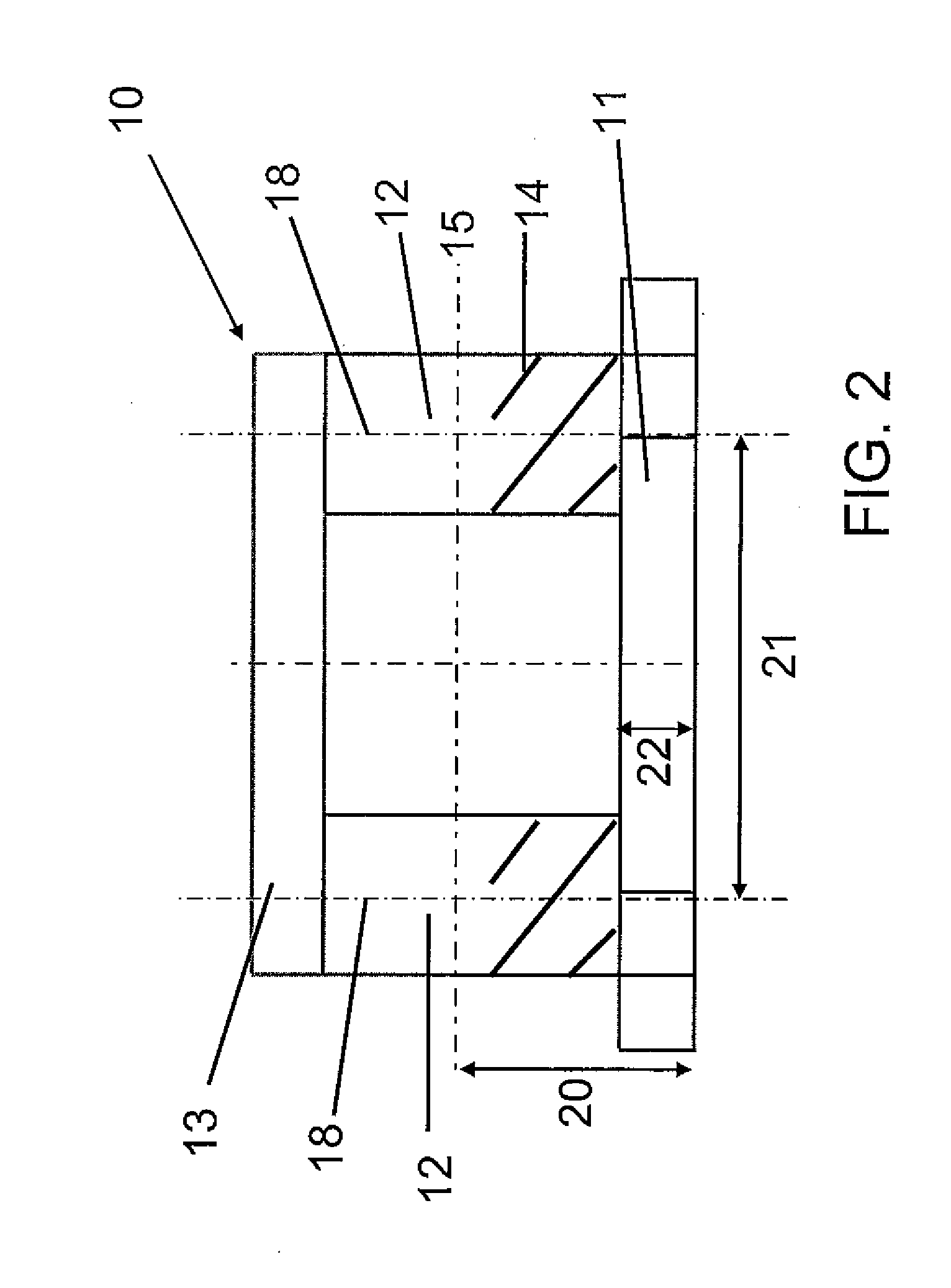
[0038]In this embodiment, parts of each column 12 can extend radially beyond the interior and exterior edges of the pontoon 11. The maximum width (in this case the diameter) 13 of the columns 12 is larger than the radial width 16 of the pontoon 11....


PUM


Abstract

An offshore floating structure (10) for the drilling and production of oil and gas includes a generally circular toroidal, hollow pontoon (11) of substantially the same radial width throughout a perimeter of the pontoon. The offshore floating structure includes a plurality of columns (12) of substantially a same cross-sectional area, each coupled at a coupling point, on a bottom end thereof to the pontoon at an equidistant point along the perimeter of the pontoon, and adapted to be coupled on a top end to a deck structure. The diameter (23) from a center of the radial width of the pontoon is greater than a distance (21) from a center of one column to a center of an adjacent column.

Description

CLAIM OF PRIORITY OR CROSS-REFERENCE TO RELATED APPLICATION[0001]This application claims the benefit of priority to Provisional Patent Application Ser. No. 61 / 416,570, filed Nov. 23, 2010, the contents of which are incorporated herein by reference in their entirety.FIELD OF THE INVENTION[0002]The present invention relates generally to an offshore floating platform for the drilling and production of oil and gas. Specifically, the invention relates to a circular cylindrical semi-submersible platform (C-Semi) for offshore drilling and production.BACKGROUND OF THE INVENTION[0003]Floating structures used for offshore oil and gas drilling and production are known. One such floating structure is conventional semi-submersible hulls. A conventional semi-submersible hull has a square pontoon structure. The square pontoon structure is coupled to four square shaped columns placed at the four corners of the pontoon structure. Therefore, the pontoon section length is the same as the length separa...

Claims


Application Information

Patent Timeline
Patent Type & Authority Applications(United States)
IPC IPC(8): B63B35/44
CPCB63B35/4413B63B1/107
Inventor WANG, TAOZENG, YIJIAN
Owner AKER SOLUTIONS AS
Learn More