Terminal processing structure and terminal processing method of coaxial cable

a terminal processing and coaxial cable technology, applied in the direction of cable/conductor manufacturing, cable termination, insulation conductor/cable, etc., can solve the problems of complex cable distal end configuration, high time and effort of terminal processing work, etc., to prevent the crimp portion of the shield terminal from reducing, and the cross-sectional size of the shield terminal can be reduced.

Inactive Publication Date: 2013-12-05
YAZAKI CORP
View PDF2 Cites 18 Cited by
  • Summary
  • Abstract
  • Description
  • Claims
  • Application Information

AI Technical Summary

Benefits of technology

[0027]According to the terminal processing structure of the coaxial cable with the configuration of the above (1), the distal end (cut end) of the braid is covered with a part of the outer sheath (the distal piece), so that the distal end of the braid can be prevented from fraying, and the fastening strength can be prevented from decreasing due to fraying of the braid. Also, the braid is not overlaid on the outer sheath and the braid crimp part of the shield terminal is crimped to the exposed part of the braid ensured between the distal piece and the proximal piece, so that a cross-sectional size of the crimp portion of the shield terminal can be decreased and occupied space can be decreased. Also, the braid is only exposed between the distal piece and the proximal piece, so that the configuration is simple, and time and effort of terminal processing work are not required. Further, the braid crimp part of the shield terminal can be directly crimped to the braid (the braid in a state of making close contact with an outer periphery of the insulator) in a state of being not overlaid on the outer sheath, so that the braid is resistant to slipping at the crimp part and a high strength of fastening to the shield terminal can be maintained.
[0028]According to the terminal processing structure of the coaxial cable with the configuration of the above (2), the braid crimp part of the shield terminal is crimped to the exposed part of the braid formed between the distal piece and the proximal piece and also, the outer sheath crimp parts formed in both sides of the braid crimp part of the shield terminal are respectively crimped to the distal piece and the proximal piece, so that the braid can surely be prevented from fraying and also, the strength of fastening between the coaxial cable and the shield terminal can be increased.
[0029]According to the terminal processing method of the coaxial cable with the configuration of the above (3), the terminal processing structure with the configuration of the above (1) is obtained by sliding a part of the outer sheath (the distal piece) to the distal end side, so that the distal end of the braid can be protected so as not to fray in a part of the outer sheath while preventing the braid from loosening.
[0030]According to the invention, the distal end of the braid can be prevented from fraying, and the fastening strength can be prevented from decreasing due to fraying of the braid. Also, the cross-sectional size of the crimp portion of the shield terminal can be decreased and the occupied space can be decreased. Also, the configuration can be simplified and also time and effort of terminal processing work are reduced. Further, the braid can be prevented from slipping at the crimp part of the shield terminal and a high strength of fastening to the shield terminal can be maintained.

Problems solved by technology

Also, since the annular projection braid part 102A or the folded braid part 102B is formed, there are problems that a configuration of the cable distal end becomes complicated and also much time and effort of terminal processing work are required.

Method used


Image

  • Terminal processing structure and terminal processing method of coaxial cable
  • Terminal processing structure and terminal processing method of coaxial cable
  • Terminal processing structure and terminal processing method of coaxial cable

Examples


Embodiment Construction

[0038]An embodiment of the invention will hereinafter be described with reference to the drawings.

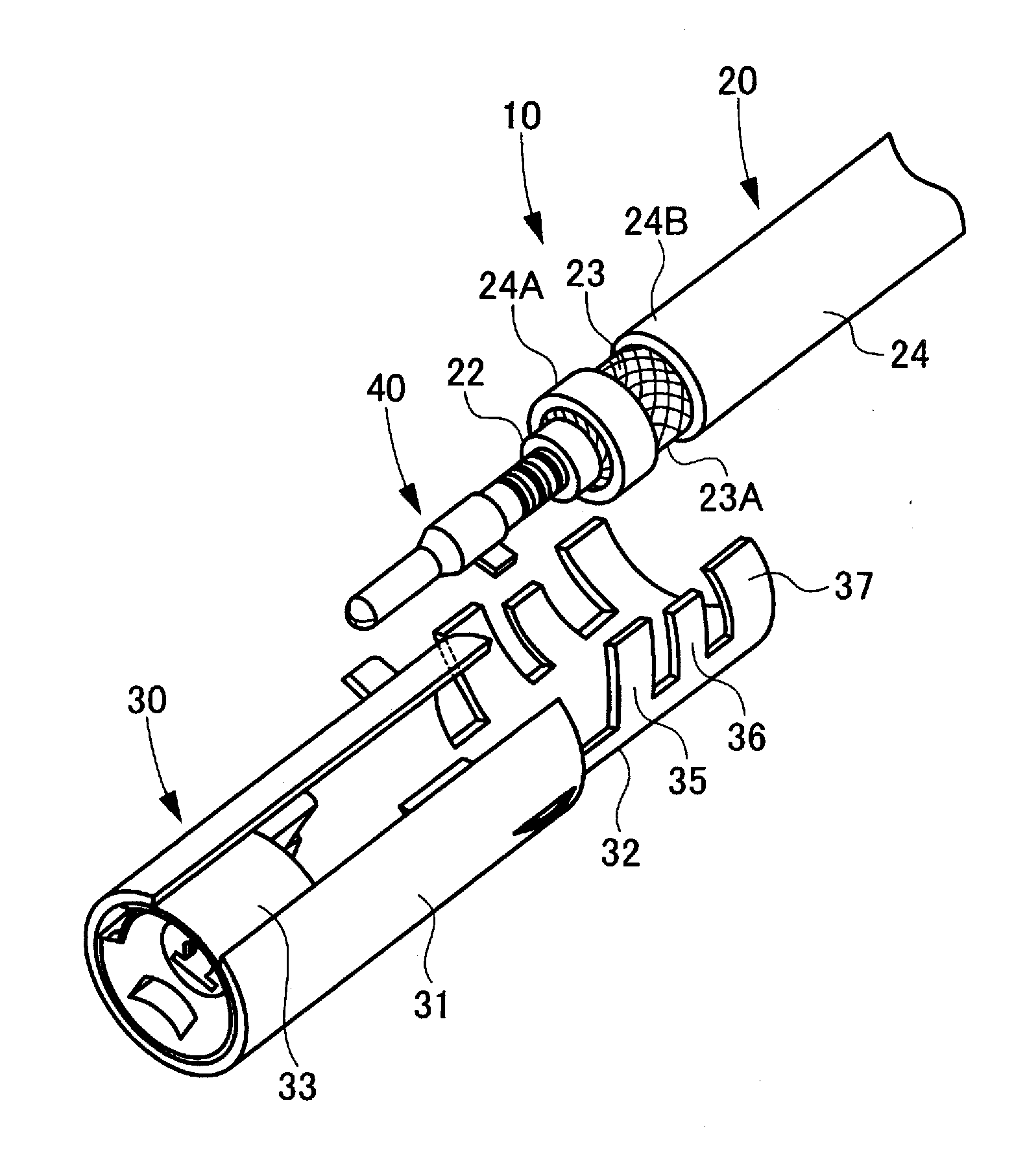
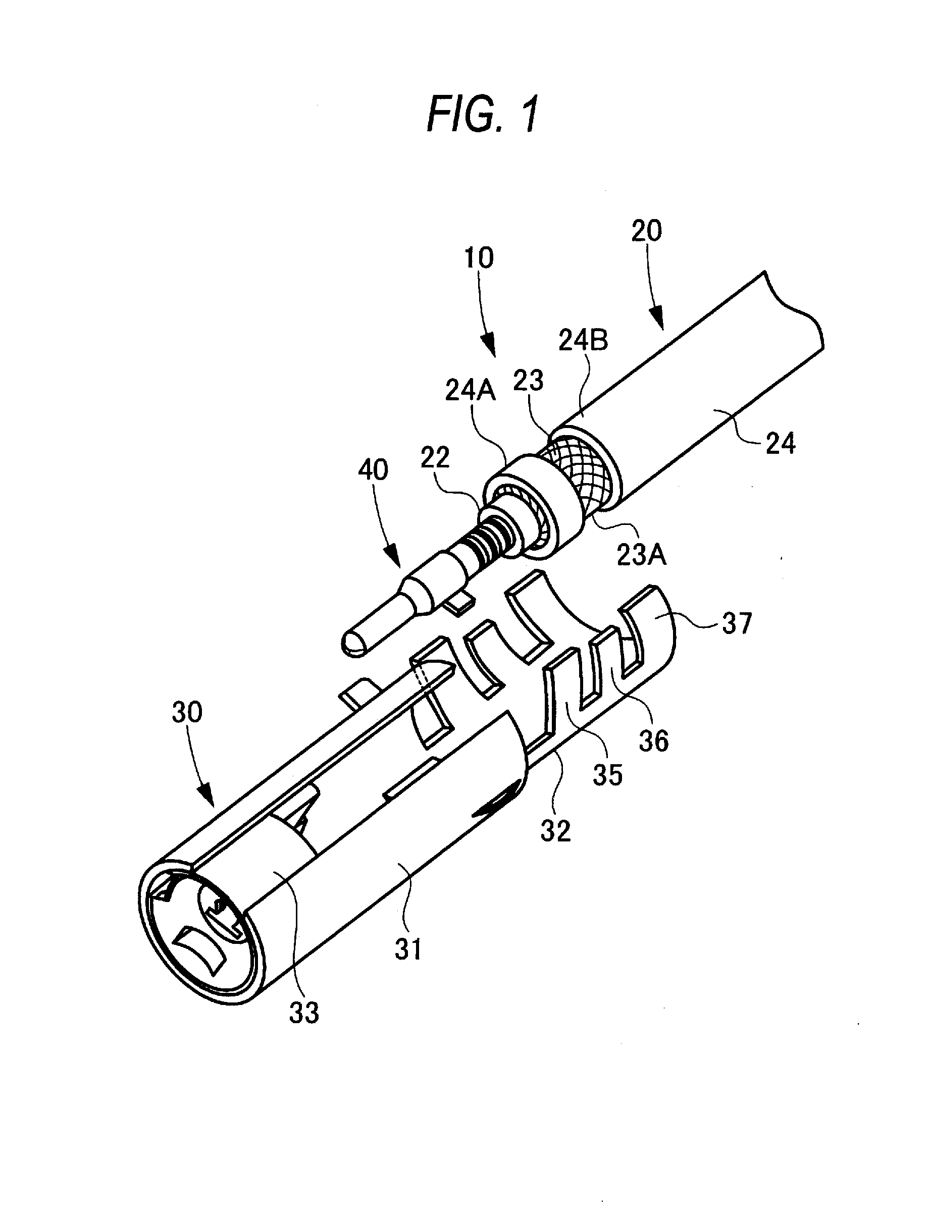
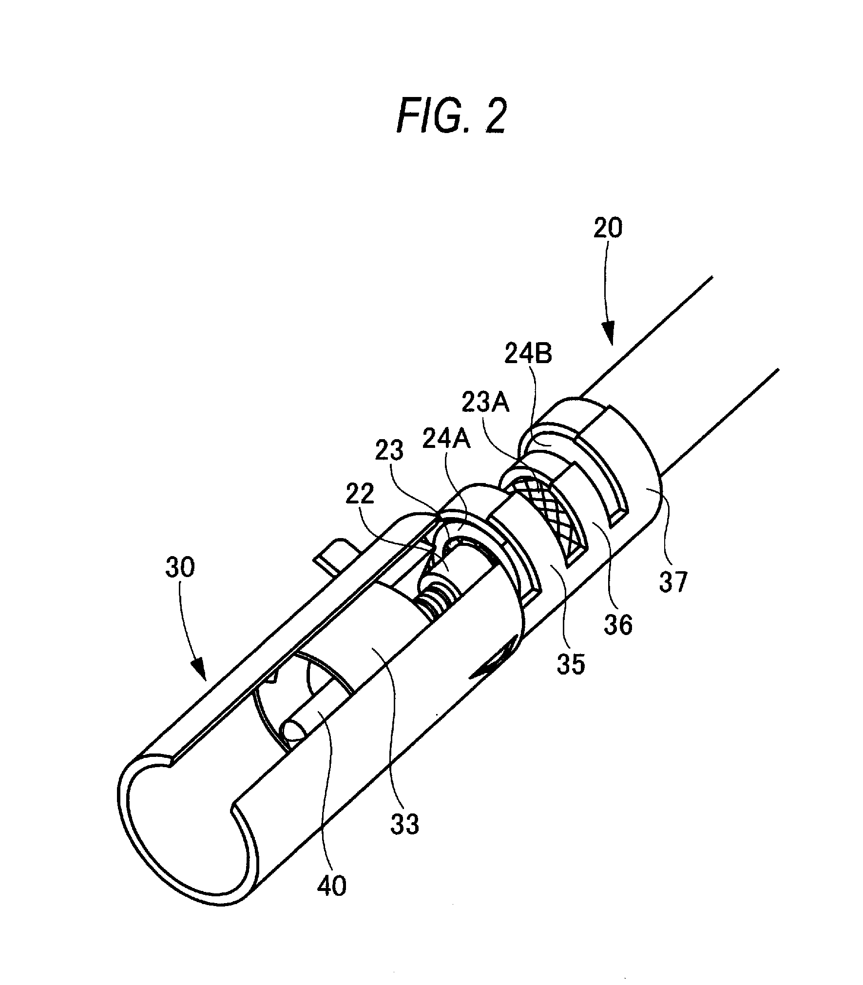
[0039]FIG. 1 is a view showing a terminal processing structure of a coaxial cable of an embodiment and is a perspective view showing a state before crimping of a shield terminal, and FIG. 2 is a perspective view showing a state after crimping of the same shield terminal, and FIGS. 3A to 3C are a step explanatory diagram of a terminal processing method of the coaxial cable.

[0040]A terminal processing structure 10 of this coaxial cable includes a coaxial cable 20, a shield terminal 30, a central conductor 40, and a dielectric 33 interposed between the shield terminal 30 and the central conductor 40.

[0041]The coaxial cable 20 includes a core wire 21, an insulator 22 with which an outer periphery of the core wire 21 is covered, a braid 23 with which an outer periphery of the insulator 22 is covered, and an outer sheath 24 with which an outer periphery of the braid 23 is covered, and the cor...


PUM

PropertyMeasurementUnit
structureaaaaaaaaaa
frequencyaaaaaaaaaa
diameteraaaaaaaaaa

Abstract

A terminal processing structure of a coaxial cable includes a core wire, an insulator with which an outer periphery of the core wire is covered, a braid with which an outer periphery of the insulator is covered, and an outer sheath with which an outer periphery of the braid is covered. The outer sheath is divided into a distal piece and a proximal piece by being notched along a circumferential direction in a cable distal end and the distal piece is held in a position separate from the proximal piece and thereby an exposed part of the braid to which a braid crimp part of a shield terminal is crimped is formed between the distal piece and the proximal piece and also a distal end of the braid is covered with the distal piece.

Description

CROSS REFERENCE TO RELATED APPLICATION[0001]This application is a continuation of PCT application No. PCT / JP2012 / 055148, which was filed on Feb. 23, 2012 based on Japanese Patent Applications No. 2011-045405 filed on Mar. 2, 2011, the contents of which are incorporated herein by reference.BACKGROUND OF THE INVENTION[0002]1. Technical Field[0003]The present invention relates to a terminal processing structure and a terminal processing method of a coaxial cable.[0004]2. Background Art[0005]A coaxial cable such as an antenna wire used in high-frequency signal transmission generally includes a core wire as a central conductor, an insulator as a dielectric with which an outer periphery of the core wire is covered, a braid as an external conductor with which an outer periphery of the dielectric is covered, and an outer sheath (also called an insulating sheath) with which an outer periphery of the braid is covered sequentially from the center toward the outside. The coaxial cable of such a...

Claims


Application Information

Patent Timeline
Patent Type & Authority Applications(United States)
IPC IPC(8): H02G15/02H01R43/048
CPCH02G15/025H01R43/048H01R4/185H01R9/0518Y10T29/49123
Inventor FURUKAWA, SHOUICHI
Owner YAZAKI CORP
Why Eureka
Try Eureka