Front vehicle body structure

Active Publication Date: 2013-12-05
SUBARU CORP
View PDF0 Cites 31 Cited by
  • Summary
  • Abstract
  • Description
  • Claims
  • Application Information

AI Technical Summary

Benefits of technology

[0009]The present invention has been designed in consideration of the circumstances described above. A first aspect of the present invention is a front vehicle body structure including a front side frame disposed at a front of a vehicle body on each side of a power unit in a vehicle width direction, the front side frame extending substantially in a fore-and-aft direction of the vehicle; and a load transfer member disposed outside in the vehicle width direction, near a front end of the front side frame, a rear end of the load transfer member being fixed to a certain position of a outer lateral side of the front side frame in the vehicle width direction, the certain position being located forwardly of a center position of the power unit in the fore-and-aft direction, a front end of the load transfer member being disposed forwardly of the rear end in the fore-and-aft direction and outwardly of the rear end in the vehicle width direction. An impact load to the front end of the load transfer member in a rearward direction of the vehicle causes a vicinity area of the fixed position of the front side frame to the rear end to be displaced in a direction in which the vicinity area approaches the power unit. With the above structure, an input load applied to the front end of the load transfer member at the time of a small overlap collision causes the front side frame to be deformed, so that the inner lateral side of the front side frame pushes a power unit such as an engine toward the opposite side of the vehicle in the vehicle width direction. The power unit, i.e., a heavy load is pushed toward the side of the vehicle opposite to the collided object, and thus the driving direction of the vehicle is changed to a direction in which a frontal collision of the vehicle with the collided object is avoided. Such a movement of the vehicle is intended to reduce an impact load to the cabin where a driver rides in. In addition, bending and deformation of the front side frame provides an energy absorption effect. Thus it is possible to provide a front body structure having a simple and light configuration which improves performance against small overlap offset collision.
[0010]Preferably, the front side frame has a low-stiffness portion which is formed rearwardly of the fixed position and configured to allow the front side frame to bend easily, the rear end of the load transfer member being fixed at the fixed position to the lateral outer side of the front side frame in the vehicle width direction. With the abo

Problems solved by technology

However, when the cabin itself is reinforced with the reinforcement member to obtain sufficient collision safety performance like the above-described conventional technology, it is necessary to absorb and transfer en

Method used


Image

  • Front vehicle body structure
  • Front vehicle body structure
  • Front vehicle body structure

Examples


embodiment 1

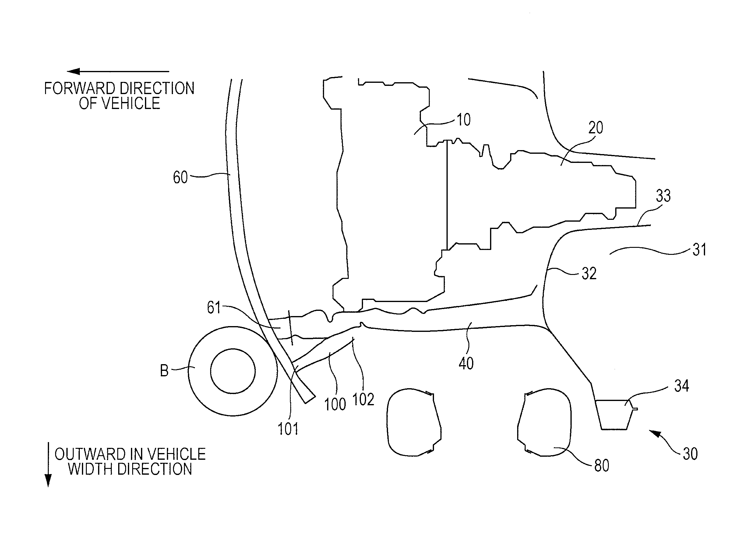
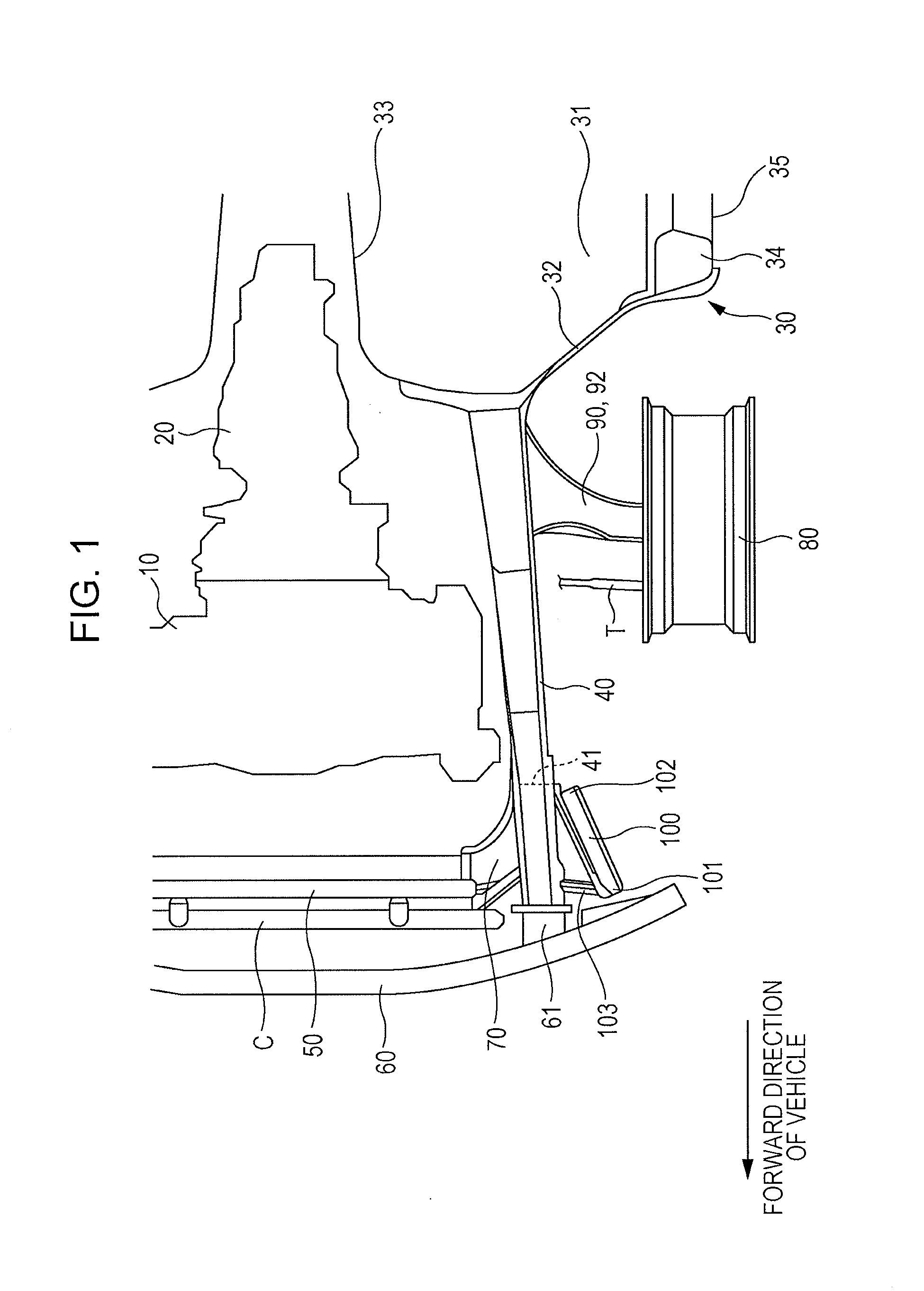
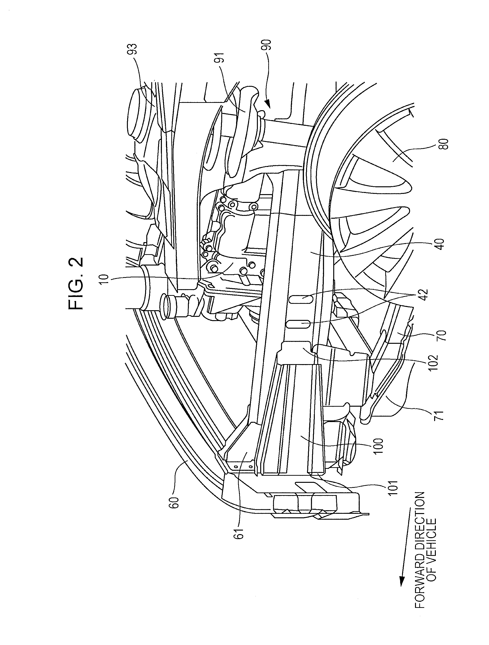
[0024]Hereinafter, a front vehicle body structure according to Embodiment 1 in the present invention will be described. The front vehicle body structure according to Embodiment 1 is applied to, for example, the body of an automobile or the like in which a power train such as an engine is mounted at the front of the automobile. FIG. 1 is a schematic plan view from above of a front vehicle body structure according to Embodiment 1. FIG. 2 is a perspective view of the front vehicle body structure according to Embodiment 1 from an obliquely upward and backward position of the outside in the vehicle width direction.

[0025]The vehicle includes an engine 10, a transmission 20, a cabin 30, front side frames 40, a radiator panel 50, a bumper beam 60, a front sub frame 70, front wheels 80, and front suspensions 90.

[0026]The engine 10 is, for example, a horizontally opposed 4-cylinder gasoline or diesel engine with 4 strokes, which is vertically mounted. The engine 10 has a cylinder head which i...

embodiment 2

[0044]Hereinafter, a front vehicle body structure according to Embodiment 2 of the present invention will be described. In the following description of Embodiment 2, substantially the same portions as those of conventional embodiments are labeled with the same reference symbols, and description is omitted and different points are mainly described. FIG. 7 is a schematic plan view illustrating the configuration of a front vehicle body structure according to Embodiment 2. In Embodiment 2, the engine 10 is, for example, a horizontally-mounted series or V-type engine, and the ends thereof in the vehicle width direction are supported by an engine mount M which is disposed to extend inward in the vehicle width direction from the front side frame 40.

[0045]In Embodiment 2, the position of the rear end 102 of the load transfer gasset 100 in the fore-and-aft direction of the vehicle is located at substantially the same position of the engine mount M or at a forward position adjacent to the eng...

embodiment 3

[0046]Hereinafter, a front vehicle body structure according to Embodiment 3 of the present invention will be described. FIG. 8 is a schematic plan view illustrating the configuration of a front vehicle body structure according to Embodiment 3. In Embodiment 3, the engine 10 is a horizontally-mounted series or V-type engine, and is supported by an engine mount which is disposed at a position other than the front side frame 40. In Embodiment 3, the fixed position of the front side frame 40 to the rear end 102 of the load transfer gasset 100 is located forward relative to a center CL of the engine 10 in the fore-and-aft direction. In the above-described Embodiment 3 also, the front side frame 40 is bent and deformed at the time of a small overlap offset collision, so that the engine 10 is pushed toward the opposite side in the vehicle width direction, and thus the effect substantially the same as the above-described effect of Embodiment 1 can be obtained. Even in the case of a horizont...


PUM


Abstract

There is provided a front vehicle body structure. The structure includes a front-side frame which is disposed on each side of a power unit in a vehicle width direction, and extends in a fore-and-aft direction; and a load-transfer member disposed outside in the width direction, near a front-end of the front-side frame, a rear end of the load-transfer member being fixed to a certain position of a outer lateral side of the front-side frame in the width direction, the certain position being located forwardly of a center of the power unit in the fore-and-aft direction, a front-end of the load-transfer member being disposed forwardly and outwardly of the rear end. A load to the front-end of the load-transfer member in a rearward direction of the vehicle causes a vicinity area of the fixed position to be displaced in a direction in which the vicinity area approaches the power unit.

Description

CROSS-REFERENCE TO RELATED APPLICATIONS[0001]The present application claims priority from Japanese Patent Application No. 2012-076579 filed on Mar. 29, 2012, the entire contents of which are hereby incorporated by reference.BACKGROUND OF THE INVENTION[0002]1. Field of the Invention[0003]The present invention relates to a front body structure of a vehicle such as an automobile, and particularly, to a front body structure having an improved performance against a small overlap offset collision.[0004]2. Description of the Related Art[0005]Safety against an offset collision has been demanded of the body structure of a vehicle such as an automobile, the offset collision being such that a side portion of the vehicle collides with an object. In recent years, particularly, an improved performance for a so-called small overlap collision in the offset collision has been demanded of the body structure of a vehicle, the small overlap collision being such that only a side portion of the vehicle i...

Claims


Application Information

Patent Timeline
IPC IPC(8): B62D21/15
CPCB62D21/152B62D25/082
Inventor KUWABARA, MITSUMASAMATSUDA, HIROYUKIMIYATA, YUTAKATAKAGI, YUSUKEHOSOKAWA, TOMOHIRO
Owner SUBARU CORP
Why Eureka
Try Eureka