
Analogue-to-digital converter

a digital converter and analog technology, applied in the field of analog-to-digital converters, can solve the problems of scale factor or gain of adc, wide manufacturing tolerance of vco transfer characteristic from input voltage to output frequency, and unpredictable digital output for a given known inpu

Active Publication Date: 2013-12-05
CIRRUS LOGIC INC
View PDF1 Cites 16 Cited by
  • Summary
  • Abstract
  • Description
  • Claims
  • Application Information

AI Technical Summary

Benefits of technology

The present invention provides an analog-to-digital converter that can receive two input signals and generate two pulse streams with different pulse rates based on the input signals. The converter includes a regulation circuit that can adjust the pulse rates of the two pulse streams to match the input signals. The regulation circuit can also adjust the gain of the converter based on the number of pulses in the pulse streams. The invention also provides methods for analog-to-digital conversion using the described converter. The technical effect of the invention is to improve the accuracy and efficiency of analog-to-digital conversion by automatically adjusting the pulse rates and gain of the converter based on the input signals.

Problems solved by technology

One problem with this type of ADC, especially when formed as, or as part of, an integrated circuit (IC), is that the VCO transfer characteristic from input voltage to output frequency may have wide manufacturing tolerances.
Thus, the frequency output for a given defined input signal may be unpredictable from IC-to-IC and / or wafer-to-wafer and hence the scale factor or gain of the ADC, i.e. the digital output for a given known input, may be unpredictable.

Method used


Image

  • Analogue-to-digital converter
  • Analogue-to-digital converter
  • Analogue-to-digital converter

Examples


Embodiment Construction

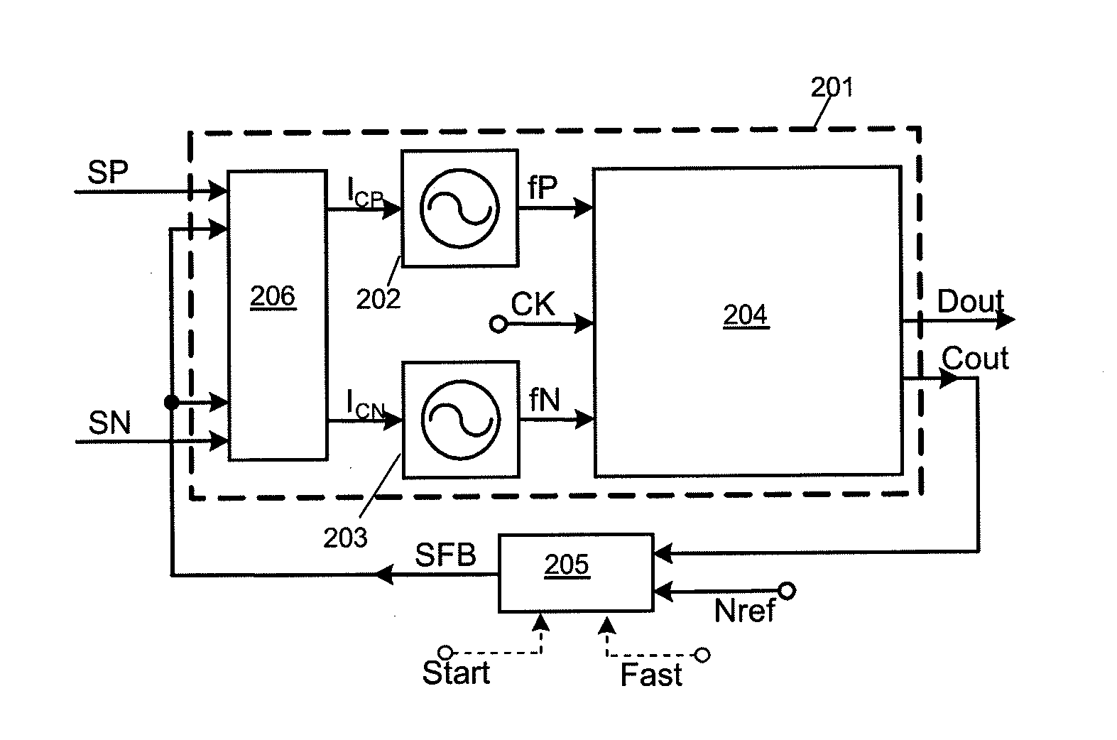
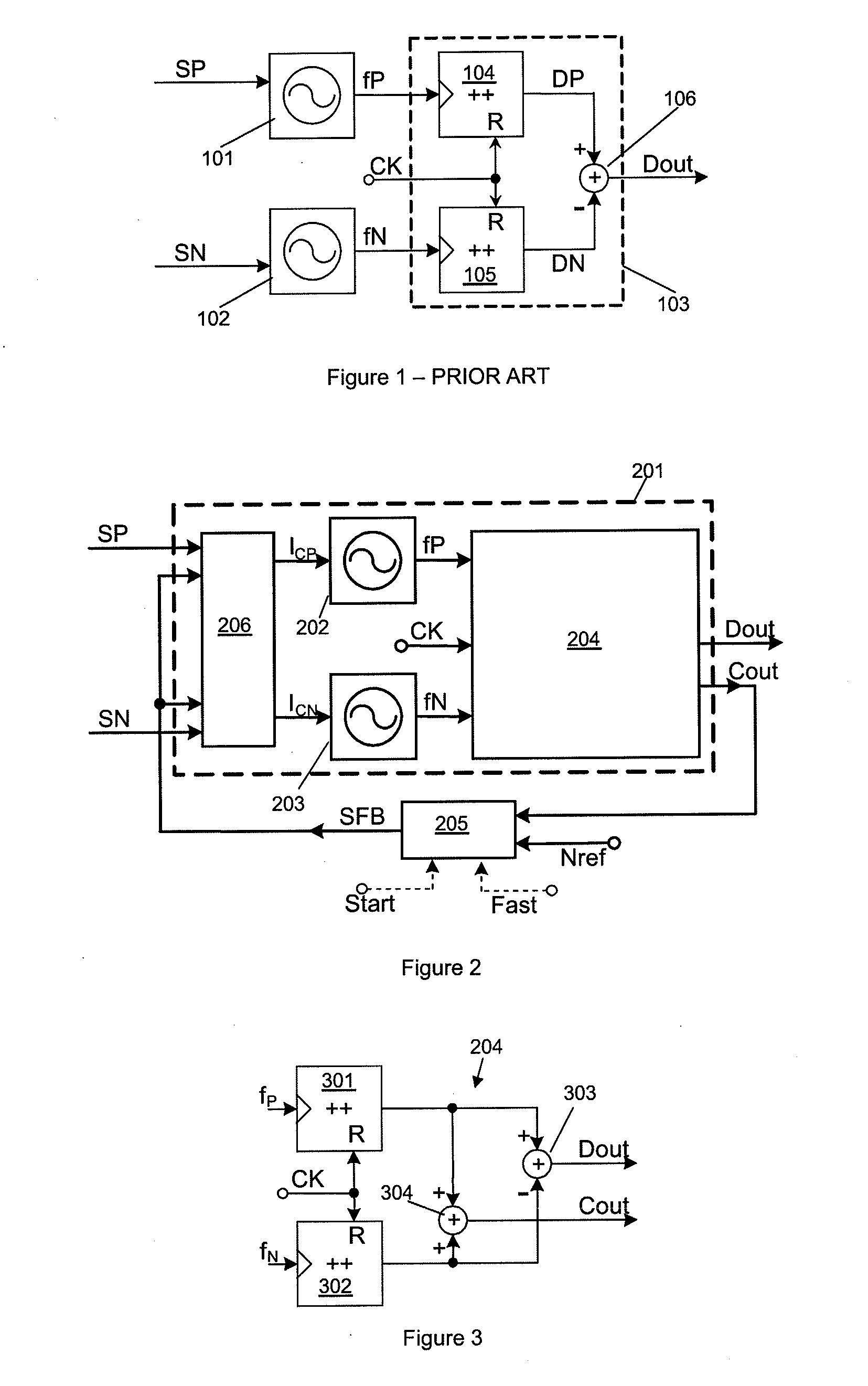
[0089]Embodiments of the present invention provide analogue-to-digital converters (ADCs) for receiving first and second input analogue signals, with controlled oscillator circuitry for generating first and second pulse streams with pulse rates dependent on the first and second input signals respectively and difference circuitry for generating a first digital signal based on the difference in number of pulses of the first and second pulse streams.

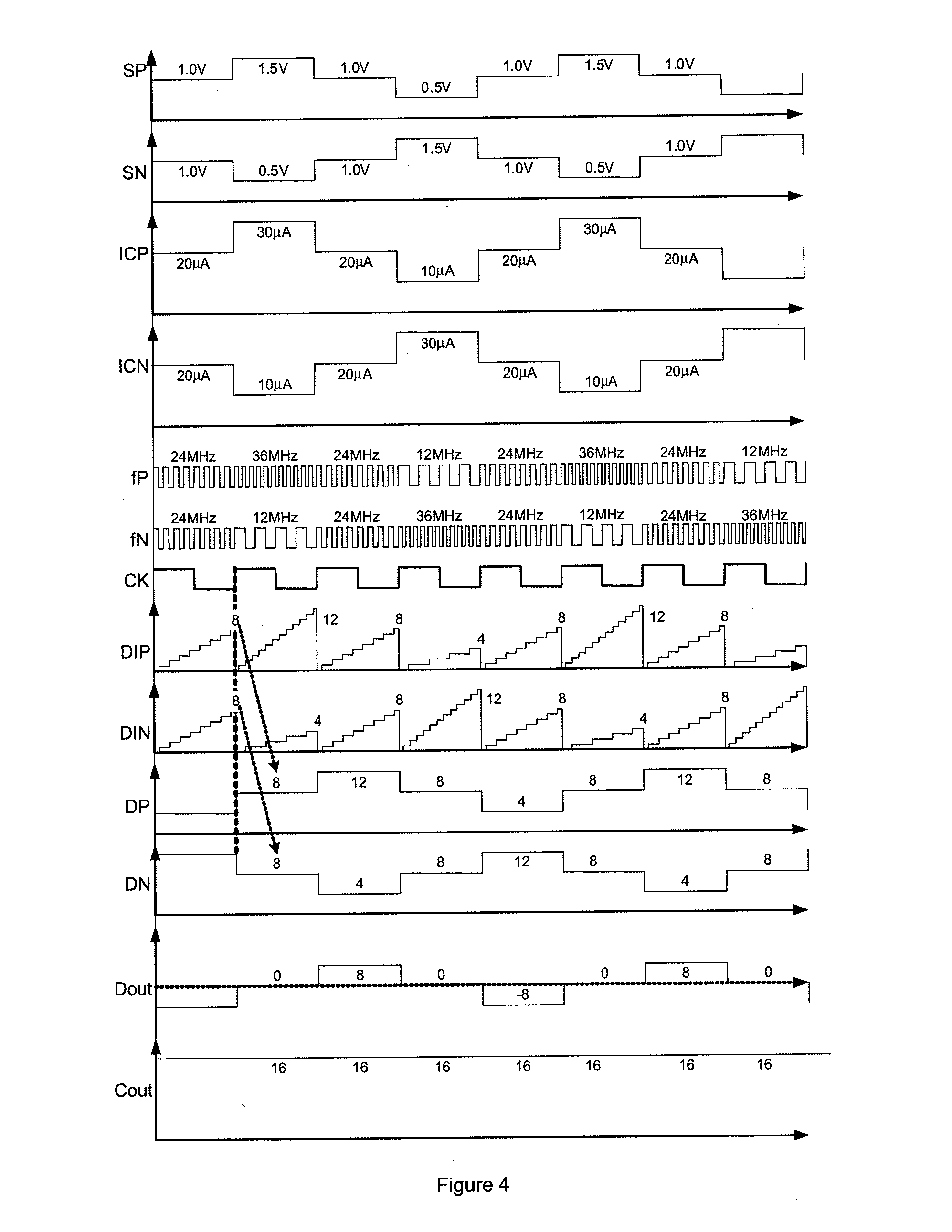
[0090]As described above, for known VCO based ADCs such as shown in FIG. 1, a variation in transfer characteristic of the VCO can lead to an unpredictable and varying digital output. As described earlier a first digital signal, Dout, is based on the difference of the number of pulses in the first and second pulse streams in a given count period. In some embodiments the first digital signal Dout may be used directly as the output of the ADC whereas in other embodiments there may be some processing or remodulation of the first digital signal b...


PUM


Abstract

An apparatus and method for regulating analogue-to-digital converters. First and second input signals are received at controlled oscillator circuitry which generates respective first and second pulse streams with pulse rates based on the relevant input signal. Difference circuitry determines the difference in number of pulses of the first and second pulse streams and outputs a first digital signal. Circuitry also determines a signal independent value based on the number of pulses of the first and / or second pulse streams. In one embodiment this value is the sum or average of the number of pulses of the first and second pulse streams. This value can be used to calibrate for any variation in transfer characteristic of the oscillator circuitry. In one embodiment this value is compared to a reference value and a regulation signal passed to control circuitry to regulate the operation of the oscillation circuitry.

Description

[0001]This application claims the benefit of U.S. Provisional Application No. 61 / 653,238, filed on May 30, 2012, the disclosure of which is incorporated by reference herein in its entirety.BACKGROUND OF THE INVENTION[0002]1. Field of the Invention The present application relates to analogue-to-digital converters having controlled oscillators and to apparatus and methods for regulating an analogue-to-digital converter to account for, or provide, a variation in oscillator transfer characteristic.[0003]2. Description of the Related Art[0004]Analogue-to-Digital converters (ADCs) using voltage controlled oscillators (VCOs) are known. FIG. 1 shows an example of a conventional ADC for differential input signals that produces a digital output based on the difference between two analogue input signals. The differential analogue input signals, SP and SN, are received by respective VCOs 101 and 102 respectively. Each VCO 101, 102 outputs a steam of pulses at a pulse rate or frequency which is ...

Claims


Application Information

Patent Timeline
Patent Type & Authority Applications(United States)
IPC IPC(8): H03M1/34
CPCH03M1/34H03M1/00H03M1/1014H03M1/186H03M1/60H03M1/0617H03M1/0619H03M1/1004H03M1/12H03M1/1225
Inventor LESSO, JOHN PAULPENNOCK, JOHN LAURENCE
Owner CIRRUS LOGIC INC
Learn More