
Anti-tamper system

a technology of anti-tampering and anti-tampering, which is applied in the direction of keyhole guards, instruments, and ways, and can solve the problems of low energy consumption reading and significant business risk in both uses of permanent magnets

Active Publication Date: 2013-12-05
IBM CORP
View PDF6 Cites 5 Cited by
  • Summary
  • Abstract
  • Description
  • Claims
  • Application Information

AI Technical Summary

Benefits of technology

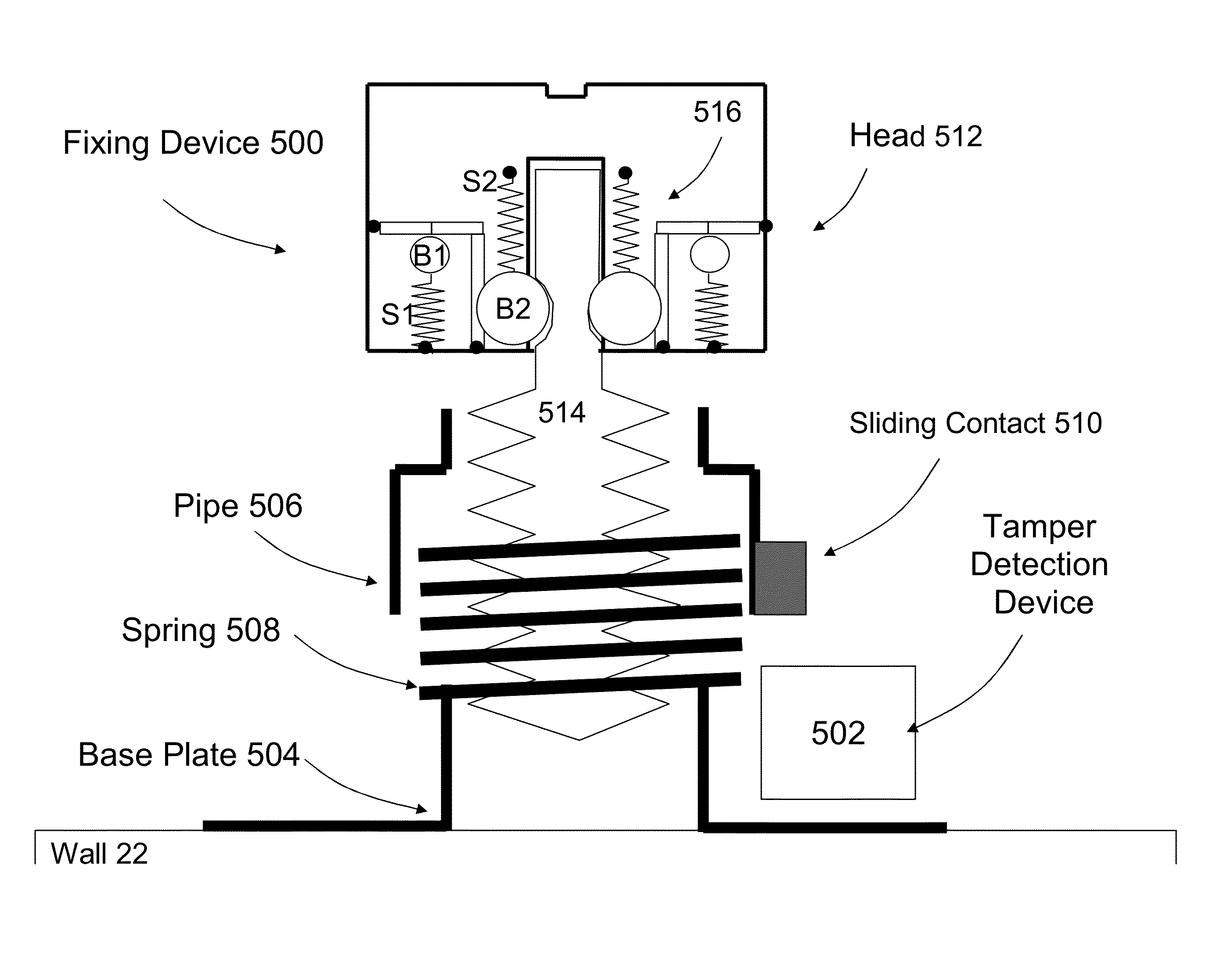
The proposed embodiments of the patent aim to minimize the impact on current meters and make it easier to detect and handle tampering events. This is done by designing a lock that requires less effort and burden to update and re-set. The lock is biased by springs in an unstable equilibrium position, which can be easily unlocked by applying a magnetic counterforce greater than the force of the springs. The use of coil springs is preferred as they are simple and elastic spring material has fewer moving parts.

Problems solved by technology

Tests have shown that magnetic tampering using a permanent magnet placed in the vicinity of a smart meter results in a lower energy consumption reading.
Both uses of permanent magnets represent a significant business risk.

Method used


Image

  • Anti-tamper system
  • Anti-tamper system
  • Anti-tamper system

Examples


Embodiment Construction

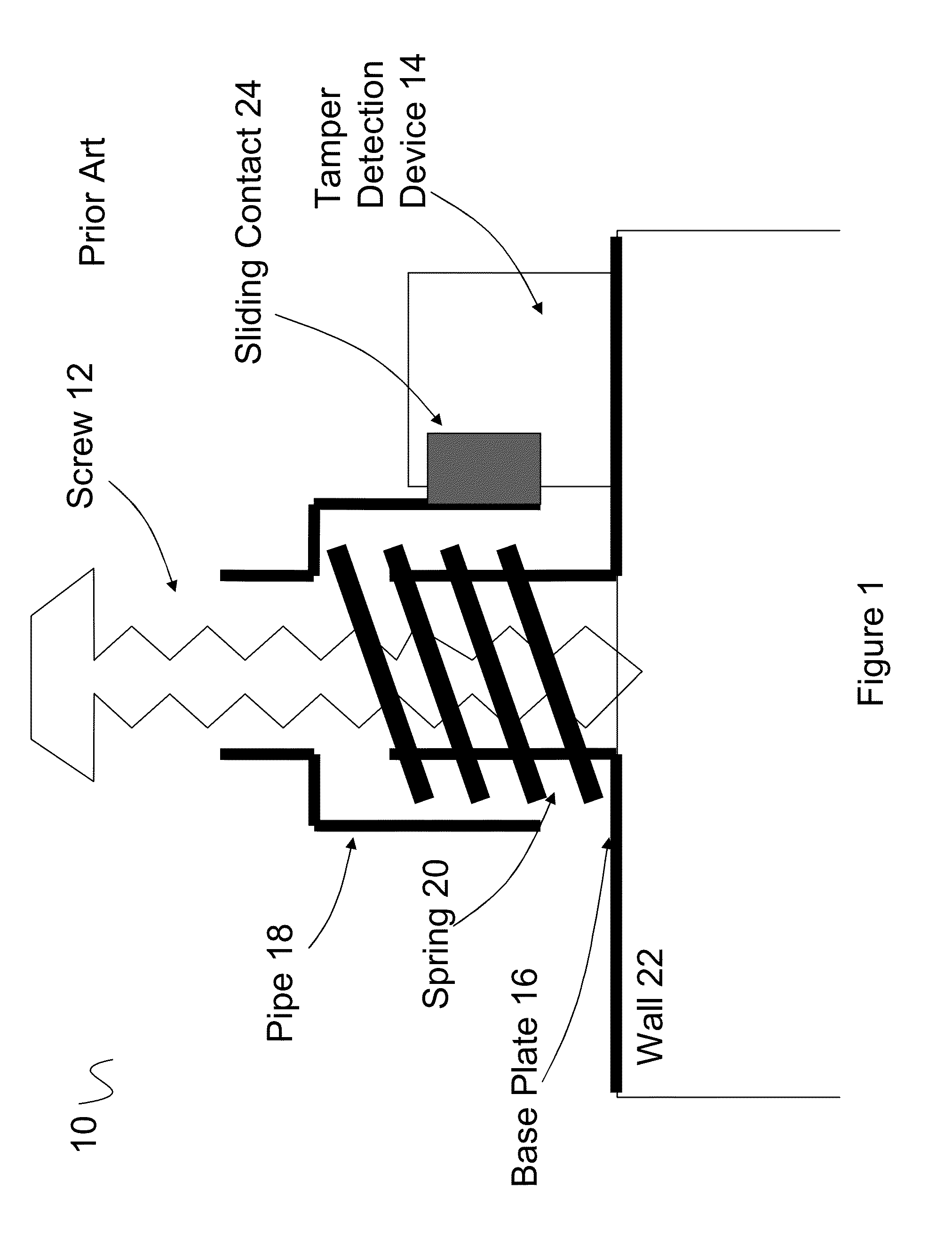
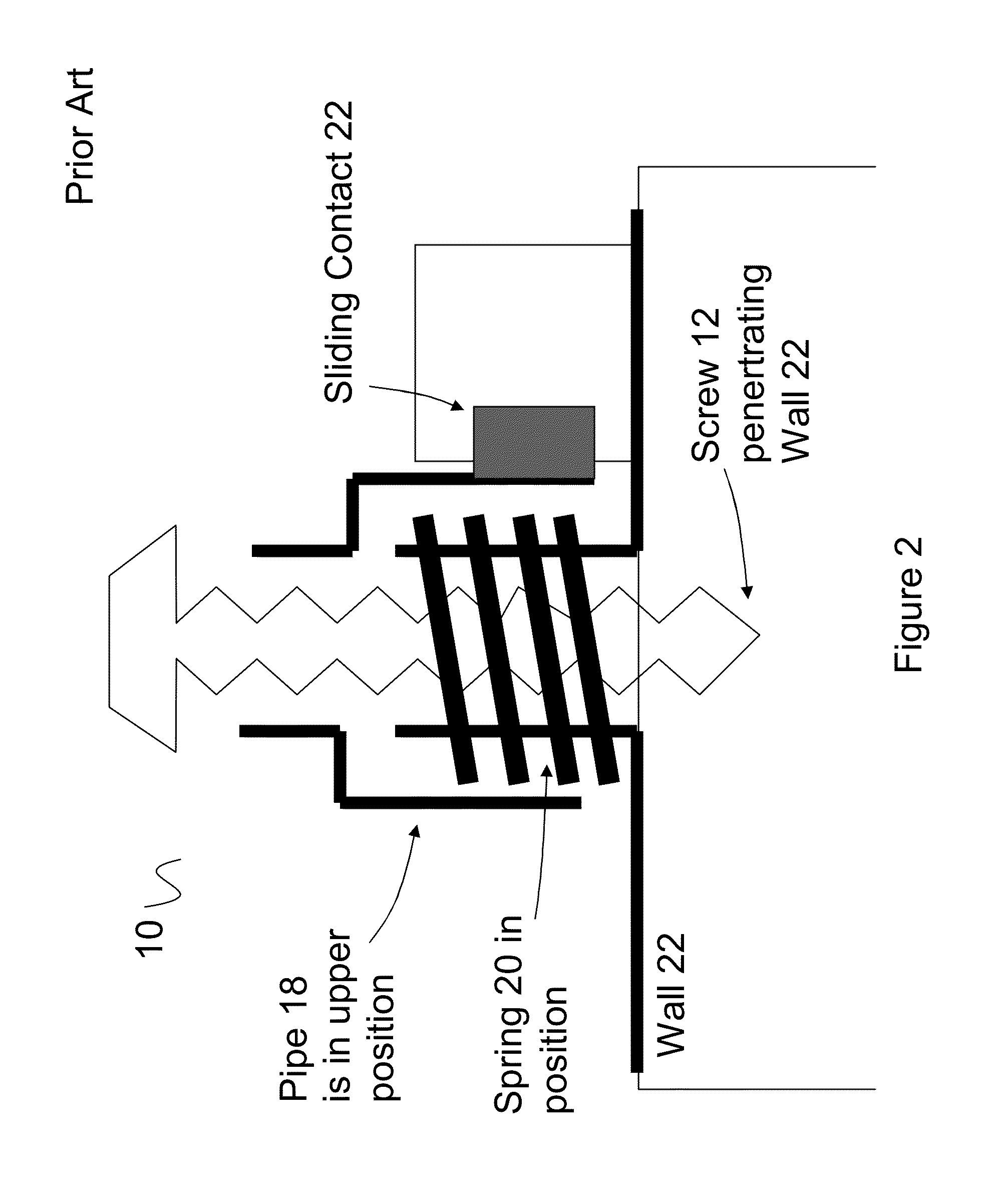
[0030]Referring to FIG. 1, a prior art anti-tamper fixture system 10 for smart meter closure is shown. The prior art anti-tamper fixture system 10 includes: a fixing device (screw 12); a tamper detection device 14; a base plate 16; a pipe 18; and a spring 20. The fixture system 10 is fixable to a wall 22 of a closure that seals a smart meter closed.

[0031]The screw 12 fixes the detection device 14 to the wall 22 and the detection device 14 will detect and record if the screw 12 is removed. This allows a service operator to tell if an unauthorized attempt has been made to open the smart meter closure.

[0032]The tamper detection device 14 is an electronic device that records when an electric circuit is broken. The pipe 18 includes a sliding contact 24 that makes an electric circuit in the tamper detection device 14 when the screw 12 fixes the tamper detection device 14 to the smart meter closure wall 22. When the screw 12 is not fixing the tamper detection device 14 to the smart meter c...


PUM


Abstract

An anti-tamper system including: a fixing device and an anti-tamper detection device; the fixing device comprising a body and a head whereby the head having a larger cross section then the body for enabling a tool to engage and drive the body into a first material layer thereby makes a firm connection with the anti-tamper detection device between the head and the first material layer; the fixing device further comprising a lock wherein the head is locked to the body by the lock where there is no external magnetic field and wherein the head becomes disengaged from the body when the lock is unlocked by an external magnetic field; and whereby the anti-tamper detection device detects and records a change the connection when the head becomes disengaged.

Description

TECHNICAL FIELD[0001]This invention relates to an anti-tamper screw. In particular the invention relates to an anti-tamper screw for detecting magnetic tampering that can be retro-fitted to an existing anti-tampering mechanism.RELATED ART[0002]The invention operates in the general environment of smart meters where an operator does not want unauthorized access to the smart meter nor magnetic tampering.[0003]Tests have shown that magnetic tampering using a permanent magnet placed in the vicinity of a smart meter results in a lower energy consumption reading. A permanent magnet placed near the meter causes a static magnetic disturbance field. Furthermore, the operational point of a current sensing technology in smart meters can be shifted by applying an external static magnetic field. As a result, the current transformer will measure less current and the meter will count less consumption. Both uses of permanent magnets represent a significant business risk.[0004]U.S. Pat. No. 4,542,337...

Claims


Application Information

Patent Timeline
Patent Type & Authority Applications(United States)
IPC IPC(8): F16B39/02F16B19/04F16B15/00
CPCF16B39/02F16B15/00F16B19/04F16B41/005E05B19/0005E05B39/00E05B65/0021E05B65/0089E05B13/001G01R22/066G01F1/56G01F1/66G06F21/86G06F21/88F16B19/00G01D11/00G01D11/24G01F15/00G01R1/18
Inventor BAUCHOT, FREDERIC J.CLEMENT, JEAN-YVESKLATOVSKY, RICARDOSAMIN, JEAN-CHRISTOPHE
Owner IBM CORP
Learn More