Turbomachinery component cooling scheme

Active Publication Date: 2013-12-05
RAYTHEON TECH CORP
View PDF4 Cites 14 Cited by
  • Summary
  • Abstract
  • Description
  • Claims
  • Application Information

AI Technical Summary

Problems solved by technology

Across these applications, turbine performance depends on the balance between higher pressure ratios and core gas path temperatu

Method used


Image

  • Turbomachinery component cooling scheme
  • Turbomachinery component cooling scheme
  • Turbomachinery component cooling scheme

Examples


Embodiment Construction

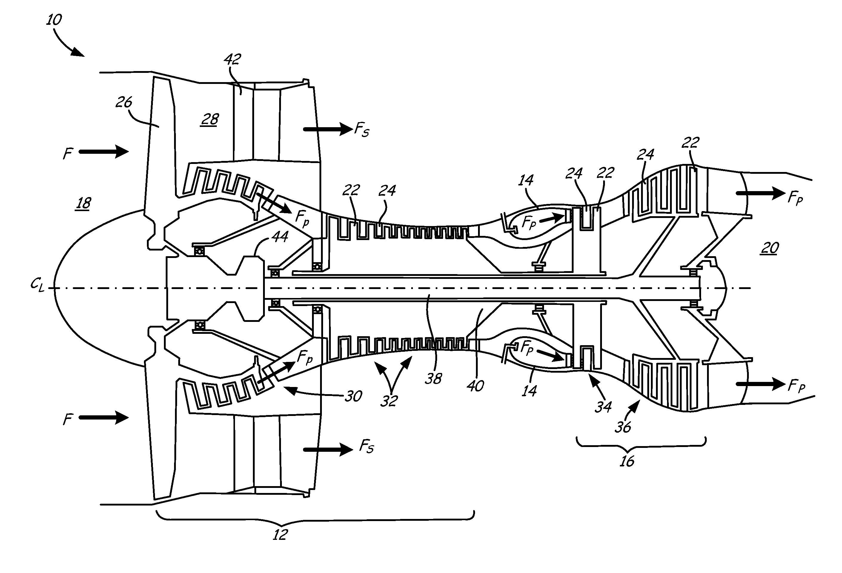
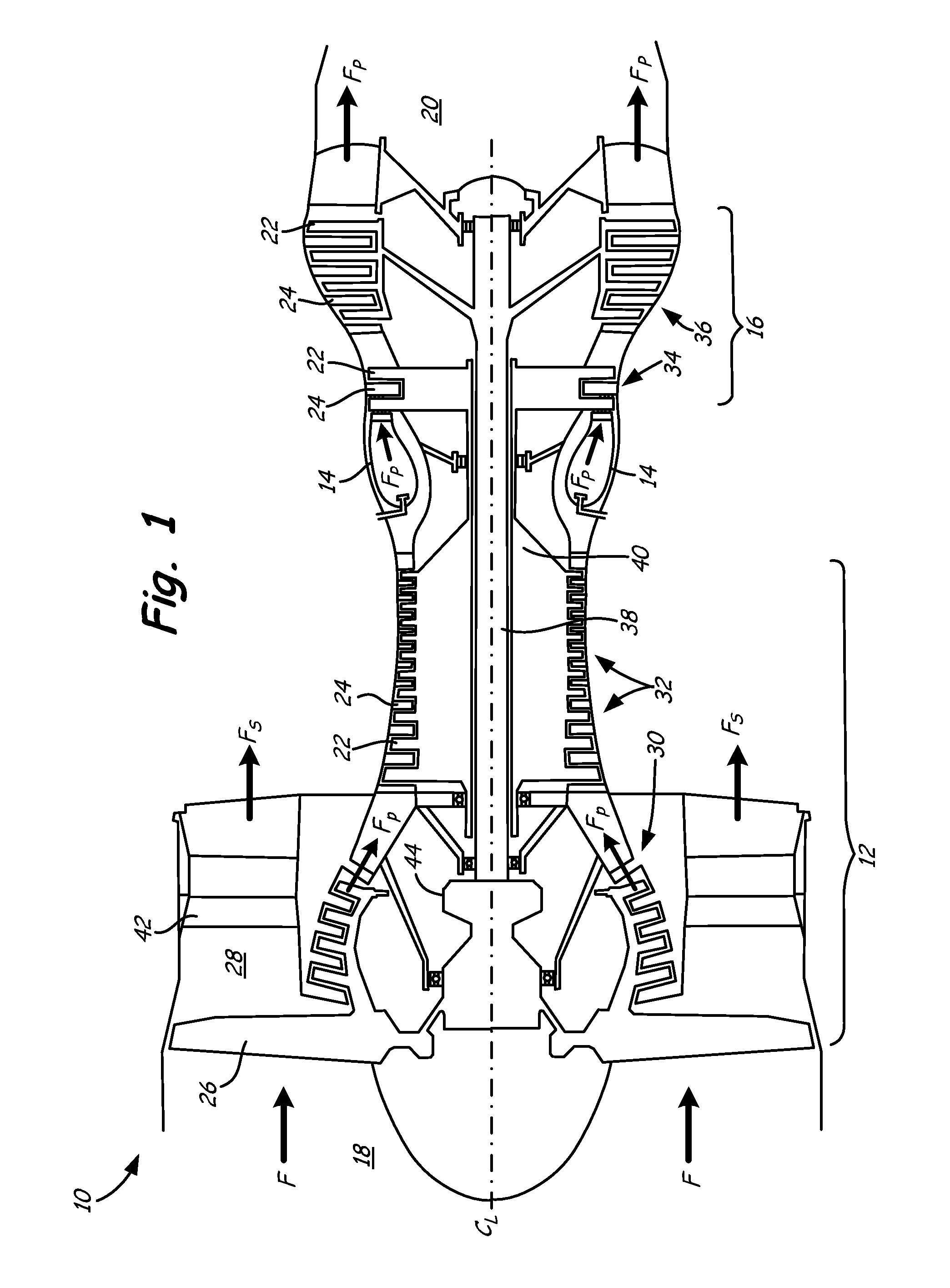
[0023]FIG. 1 is a cross-sectional view of gas turbine engine 10. Gas turbine engine (or turbine engine) 10 includes a power core with compressor section 12, combustor 14 and turbine section 16 arranged in flow series between upstream inlet 18 and downstream exhaust 20. Compressor section 12 and turbine section 16 are arranged into a number of alternating stages of rotor airfoils (or blades) 22 and stator airfoils (or vanes) 24.

[0024]In the turbofan configuration of FIG. 1, propulsion fan 26 is positioned in bypass duct 28, which is coaxially oriented about the engine core along centerline (or turbine axis) CL. An open-rotor propulsion stage 26 may also provided, with turbine engine 10 operating as a turboprop or unducted turbofan engine. Alternatively, fan rotor 26 and bypass duct 28 may be absent, with turbine engine 10 configured as a turbojet or turboshaft engine, or an industrial gas turbine.

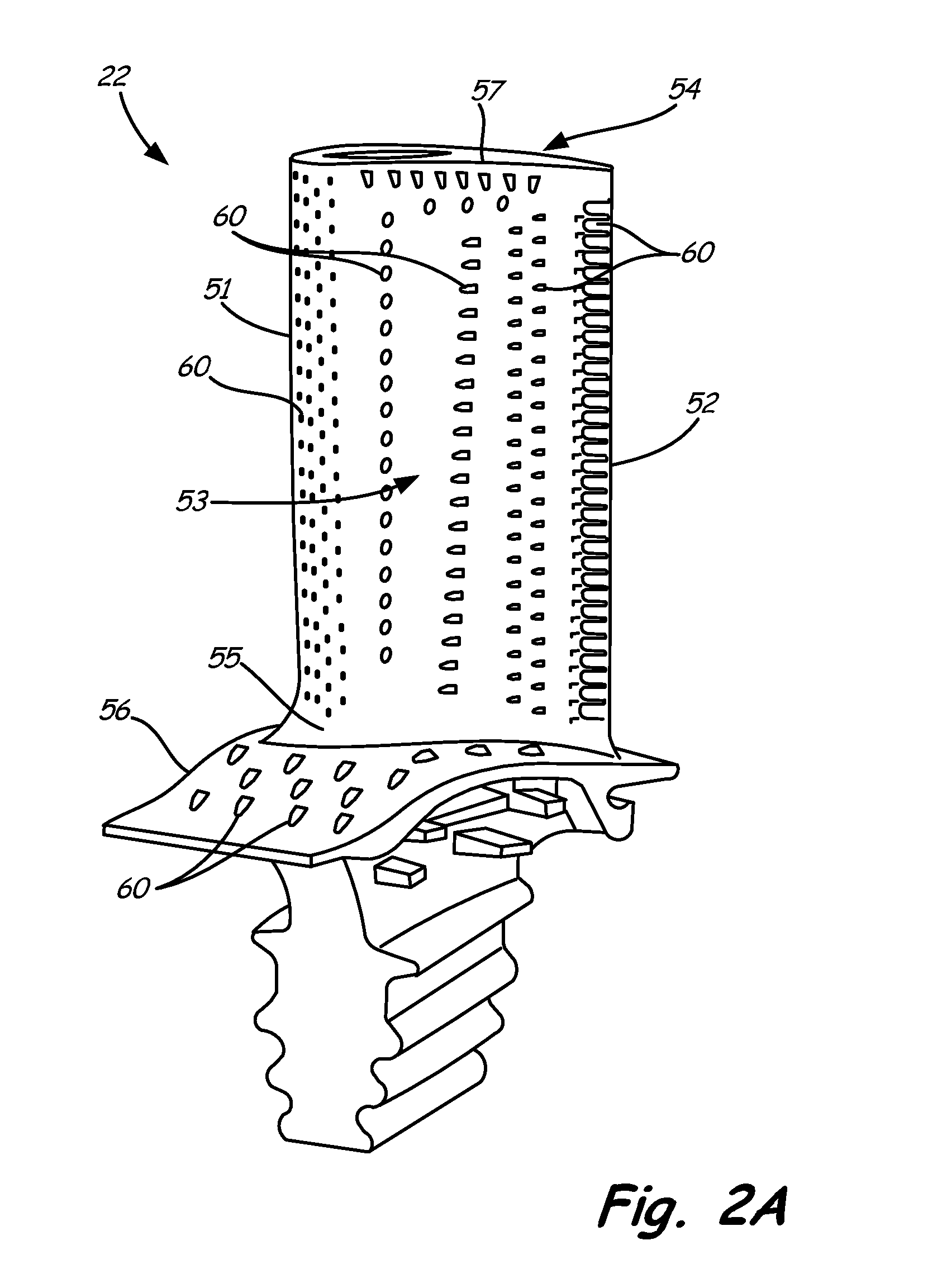
[0025]For improved service life and reliability, components of gas turbine engine 10 are...


PUM


Abstract

A turbomachinery component includes a surface exposed to hot working fluid flow. The surface has an undulating contour formed from a series of alternating protuberances and troughs. A set of three cooling outlets is associated with each trough.

Description

BACKGROUND[0001]This invention relates generally to turbomachinery, and specifically to turbine flow path components for gas turbine engines. In particular, the invention relates to cooling techniques for airfoils and other gas turbine engine components exposed to hot working fluid flow, including, but not limited to, rotor blades and stator vane airfoils, endwall surfaces including platforms, shrouds and compressor and turbine casings, combustor liners, turbine exhaust assemblies, thrust augmentors and exhaust nozzles.[0002]Gas turbine engines are rotary-type combustion turbine engines built around a power core made up of a compressor, combustor and turbine, arranged in flow series with an upstream inlet and downstream exhaust. The compressor section compresses air from the inlet, which is mixed with fuel in the combustor and ignited to generate hot combustion gas. The turbine section extracts energy from the expanding combustion gas, and drives the compressor section via a common ...

Claims


Application Information

Patent Timeline
IPC IPC(8): F01D5/18
CPCF01D5/18F01D5/186F01D5/187F05D2240/11F05D2240/122F05D2240/304F05D2260/20Y02T50/60F05D2240/305F05D2250/611F05D2260/202
Inventor MARTIN, THOMAS J.STAROSELSKY, ALEXANDERZELESKY, MARK F.SLAVENS, THOMAS N.
Owner RAYTHEON TECH CORP
Why Eureka
Try Eureka