Wall plaque with decorative graphic and methods of making the same

a wall plaque and decorative technology, applied in the direction of lamination ancillary operations, display means, instruments, etc., can solve the problems of time-consuming, paper or film may become warped or wavy, and it is difficult or impossible to laminate warped or wavy paper to a face panel, so as to improve the efficiency of the manufacturing process both in cost and time.

Active Publication Date: 2013-12-12
QUORUM GRP
View PDF27 Cites 20 Cited by
  • Summary
  • Abstract
  • Description
  • Claims
  • Application Information

AI Technical Summary

Benefits of technology

[0007]One or more implementations of the present invention solve one or more of the foregoing or other problems in the art with provide systems, apparatus, and methods for precisely placing a graphic in a desired position between a face panel and a rear panel. In particular, implementations of the present invention comprise wall plaques having graphics that are printed directly to the back surface of face panels. As such, implementations of the present invention can help ensure that the graphic is flat on the back surface of the face panel and is not misaligned. In addition, one or more implementations can help to eliminate the possibility that the graphic will wrinkle, tear, or otherwise sustain damage prior to, or during manufacturing. Implementations of the present invention can also make the manufacturing process more efficient both in terms of cost and time.

Problems solved by technology

Creating a graphic by printing information onto a sheet of paper or film and laminating the graphic layer between sheets can lead to a variety of problems.
For example, when a significant amount of ink is applied to paper or film, the paper or film may become warped or wavy.
It may be difficult or impossible to laminate warped or wavy paper to a face panel.
Trimming a graphic may lead to errors and is time consuming.
Either way, this can also lead to an increased potential for error and manufacturing cost.
Even if these problems are avoided, others problems may arise during the lamination process.
For example, when laminating a graphic layer between face and back panels, the graphic may easily move and become misaligned or crooked.
Alternatively, the lamination process may cause a graphic to wrinkle, rip, or otherwise damage the graphic during the lamination process.
Each of these scenarios, and others, may lead to the creation of a plaque having a graphic that is in part or in whole unreadable or otherwise undesirable.
Accordingly, there are a number of problems that exist with conventional plaques and the manufacturing processes used to create wall plaques.

Method used


Image

  • Wall plaque with decorative graphic and methods of making the same
  • Wall plaque with decorative graphic and methods of making the same
  • Wall plaque with decorative graphic and methods of making the same

Examples


Embodiment Construction

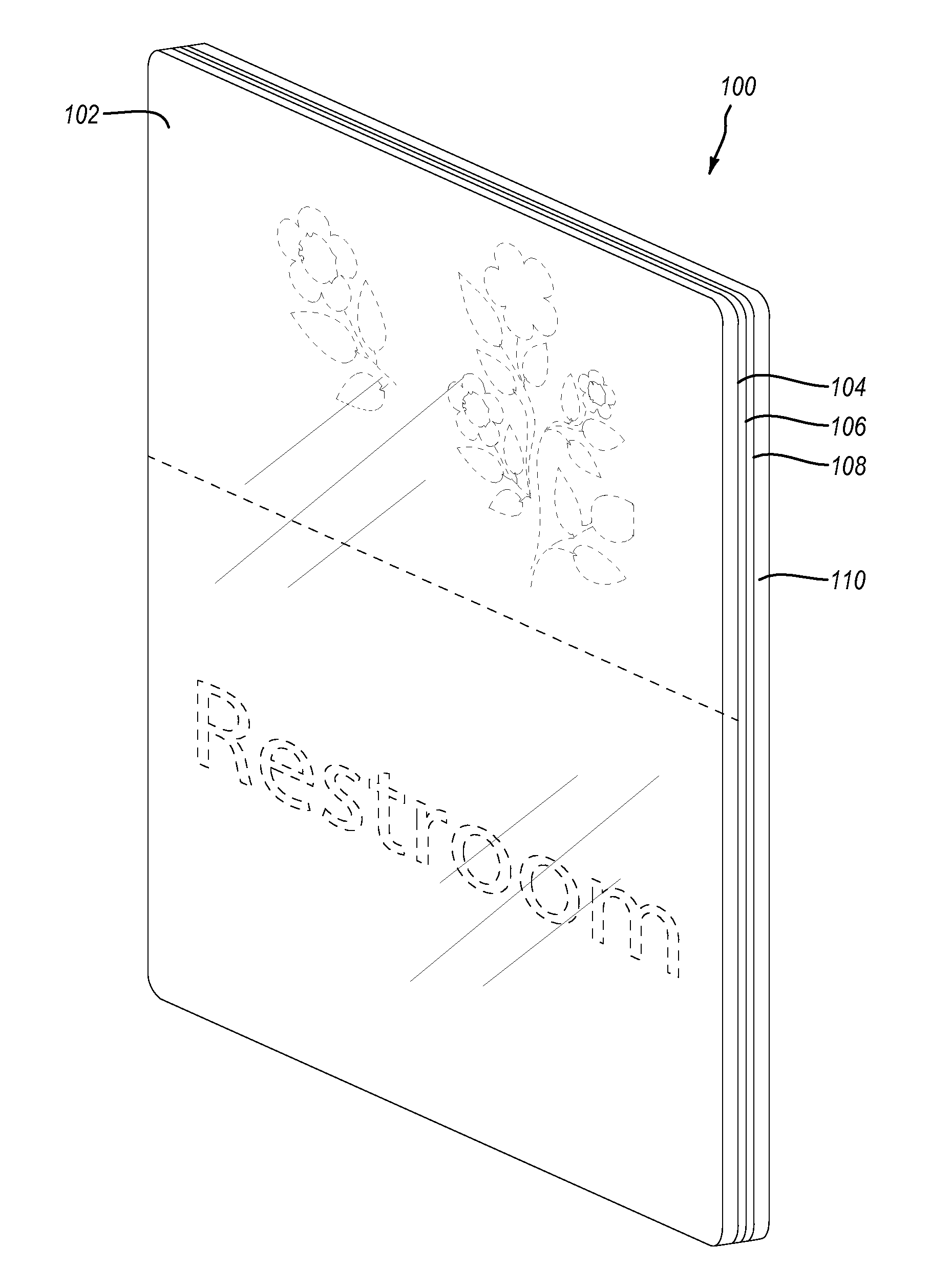
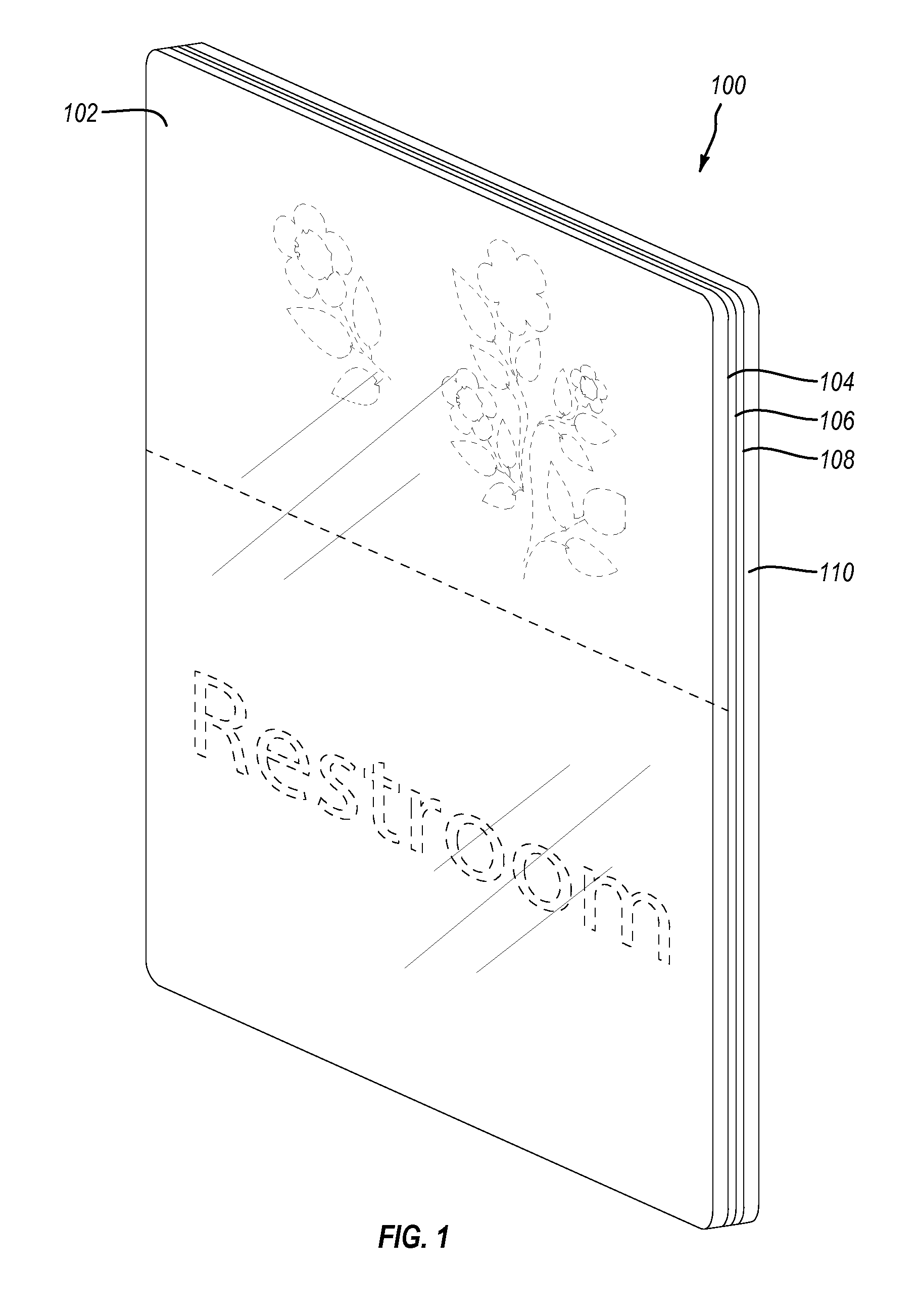
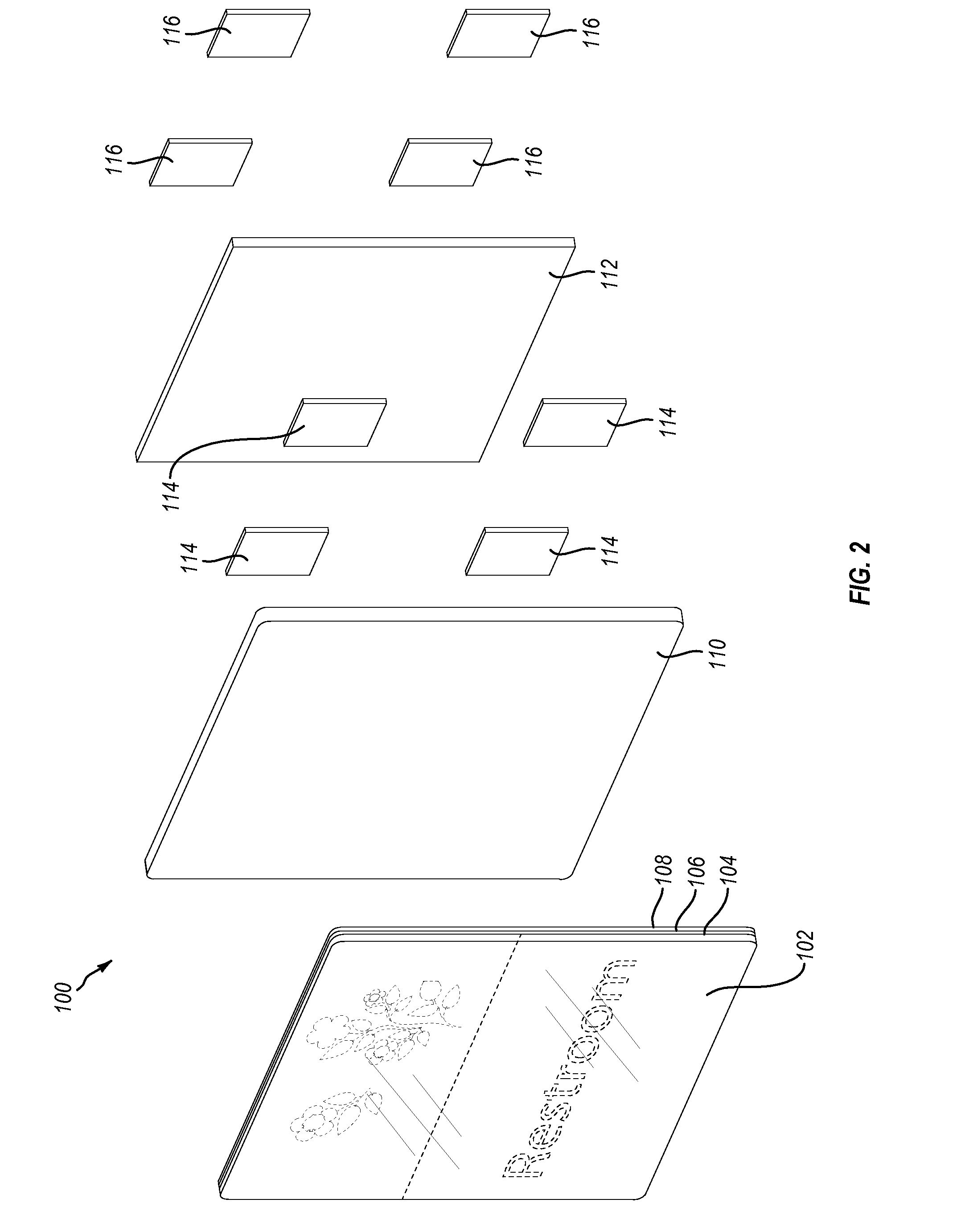
[0021]Implementations of the present invention provide systems, apparatus, and methods for precisely placing a graphic in a desired position between a face panel and a rear panel. In particular, implementations of the present invention comprise wall plaques having graphics that are printed directly to the back surface of face panels. As such, implementations of the present invention can help ensure that the graphic is flat on the back surface of the face panel and is not misaligned. In addition, one or more implementations can help to eliminate the possibility that the graphic will wrinkle, tear, or otherwise sustain damage prior to, or during manufacturing. Implementation of the present invention can also make the manufacturing process more efficient both in terms of cost and time.

[0022]By printing a graphic directly to the back surface of a face panel, the time and expense associated with printing a graphic on a sheet of paper and laminating that paper to a face panel may be avoid...


PUM

PropertyMeasurementUnit
transparentaaaaaaaaaa
semi-transparentaaaaaaaaaa
pressureaaaaaaaaaa

Abstract

Implementations of the present invention provide systems, apparatus, and methods for precisely placing a graphic in a desired position between a face panel and a rear panel. In particular, implementations of the present invention comprise wall plaques having graphics that are printed directly to the back surface of face panels. Printing a graphic directly to the back surface of a face panel may help to ensure that the graphic is flat on the back surface of the face panel and is not misaligned. In addition, printing a graphic directly to the back surface of a face panel may help to eliminate the possibility that the graphic will be wrinkled, torn, or otherwise damaged prior to being laminated on the back surface of a face panel. Implementations of the present invention may also make the manufacturing process more efficient both in terms of cost and time.

Description

BACKGROUND1. Background and Relevant Art[0001]Individuals and / or businesses often use wall plaques as a way to provide notices and display a variety of different information. Conventional wall plaques may include a graphic that is positioned between a transparent or semi-transparent face panel and a rear panel. The graphic within a plaque may identify the location of different offices within a building or identify the individual or individuals that work within a specific office. Other plaques may be used to identify building entrances / exits, bathrooms, emergency exit maps, elevator / stairs locations, and the like.[0002]Individuals and / or businesses may place these plaques in high visibility areas. For example, plaques may hang from overhead structures, such as ceilings, or secure to vertical surfaces, such as walls. These plaques may hang indoors or outdoors and may include a variety of different shapes and sizes.[0003]The graphic of conventional wall plaques typically include a shee...

Claims


Application Information

Patent Timeline
Patent Type & Authority Applications(United States)
IPC IPC(8): G09F7/00B32B37/12B32B38/10G09F7/10
CPCB32B37/12G09F7/00G09F7/10B32B38/06B32B38/145B32B2310/0831B32B2590/00B32B37/24B32B2037/243G09F7/08G09F7/14
Inventor LYONS, KURT WILLIAMPHILLIPS, CHRISTOPHER MICHAEL
Owner QUORUM GRP
Why Eureka
Try Eureka