Evaporated fuel treatment device

a technology of evaporation fuel and treatment device, which is applied in the direction of combustion air/fuel air treatment, separation process, machines/engines, etc., can solve the problems of increased cost, increased cost, and increased cost, so as to reduce the thickness of elastic molding material, prevent the removal of the retainer member, and reduce the cost

Inactive Publication Date: 2013-12-12
MAHLE FILTER SYST JAPAN CORP
View PDF6 Cites 3 Cited by
  • Summary
  • Abstract
  • Description
  • Claims
  • Application Information

AI Technical Summary

Benefits of technology

[0024]Upon assembling the evaporated fuel treatment device according to the present invention, a predetermined amount of the granular adsorbent is filled in the one open-ended casing body, and the air permeable member and the retainer member are stacked on the granular adsorbent in this order. Subsequently, the retainer member is pushed into the casing body before closing the one open end of the casing body by the cover. Since the tooth-shaped positioning retention mechanism enables positioning and retention of the retainer member in an optional position relative to the casing body in the pushing direction of the retainer member, a pushing force being applied to the retainer member is released at a time in which the air permeable member is appropriately compressively deformed. As a result, the retainer member can be held and retained in the optional position so that removal of the retainer member from the casing body can be prevented. In addition, the air permeable member can be held in the compressively deformed state.
[0025]The evaporated fuel treatment device according to the present invention can attain the following effects. As compared to an evaporated fuel treatment device using a compression coil spring made of metal in a pressing retention structure for activated carbon, the evaporated fuel treatment device according to the present invention can serve to reduce a cost thereof. Further, the evaporated fuel treatment device according to the present invention can adsorb variation in position of an end surface of an adsorbent layer accommodated within a casing without excessively compressing and deforming such an elastic molding material as a urethane foam. Further, the evaporated fuel treatment device according to the present invention can stably maintain a suitably compressed and deformed state of the elastic molding material, and can serve to minimize a thickness of the elastic molding material. Accordingly, the evaporated fuel treatment device according to the present invention can ensure a sufficient air permeability necessary to the elastic molding material and can enhance durability of the elastic molding material.
[0026]Especially, in the evaporated fuel treatment device according to the present invention, a tooth-shaped positioning retention mechanism is constituted of a combination of a toothed grooved portion and a toothed projection portion. With this construction, once the retainer member has been pushed into the casing, the toothed grooved portion and the toothed projection portion are meshed with each other so that the retainer member cannot be removed from the casing. As a result, positioning and retention of the permeable member and the retainer member relative to the casing can be more enhanced by the tooth-shaped positioning retention mechanism.

Problems solved by technology

However, in a case where the metallic compression coil spring is used in the pressing retention structure for the activated carbon, an excellent elastic characteristic can be attained but an increased cost should be caused.
As a result, there is a fear that air-flow resistance becomes too large to ensure a necessary air permeability.
In addition, there still remains such a problem that the urethane foam is deteriorated in durability due to adverse influence by permanent set in fatigue or the like which is caused by using the urethane foam in the excessively compressed and deformed manner.

Method used


Image

  • Evaporated fuel treatment device
  • Evaporated fuel treatment device
  • Evaporated fuel treatment device

Examples


first embodiment

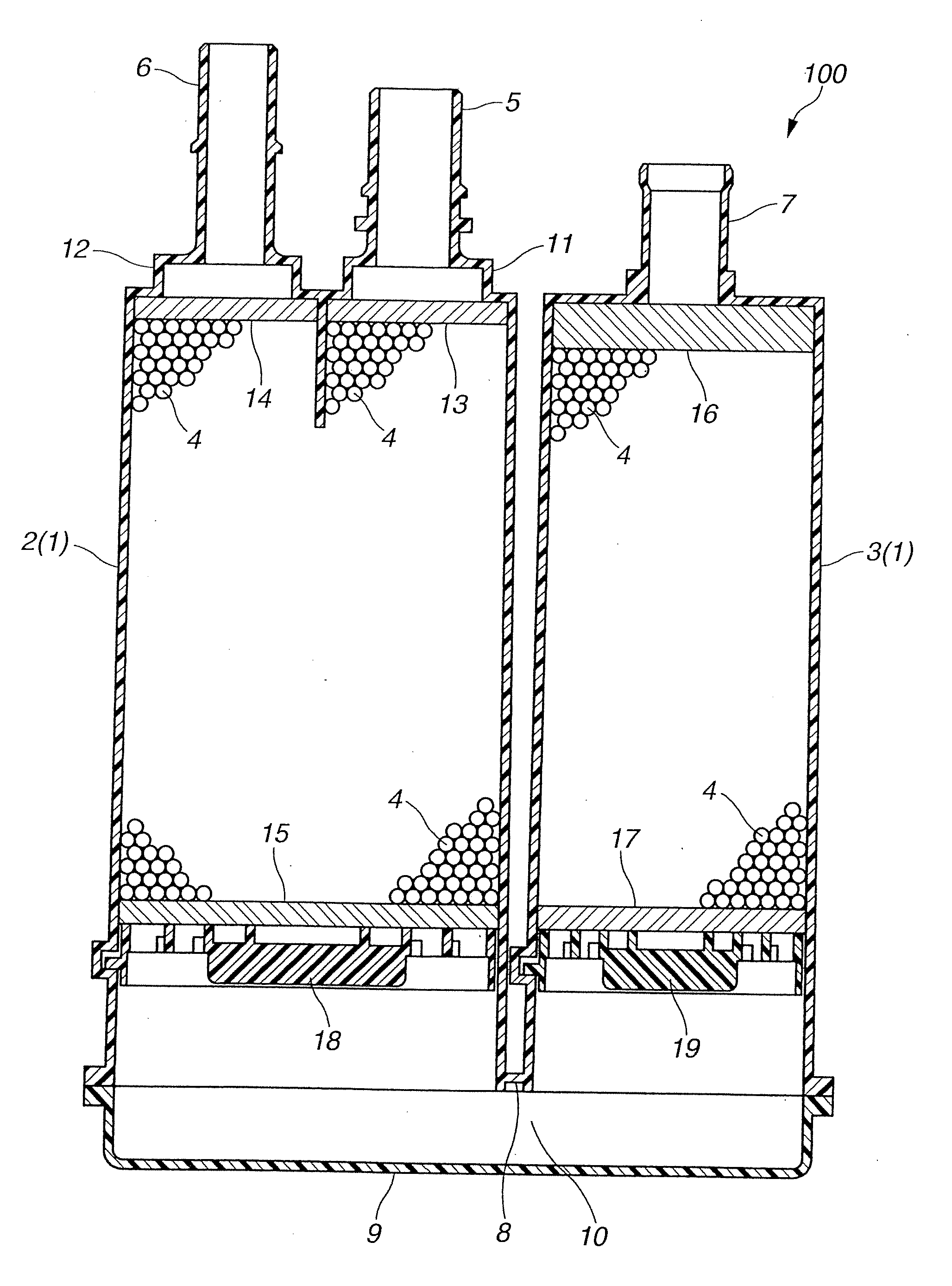
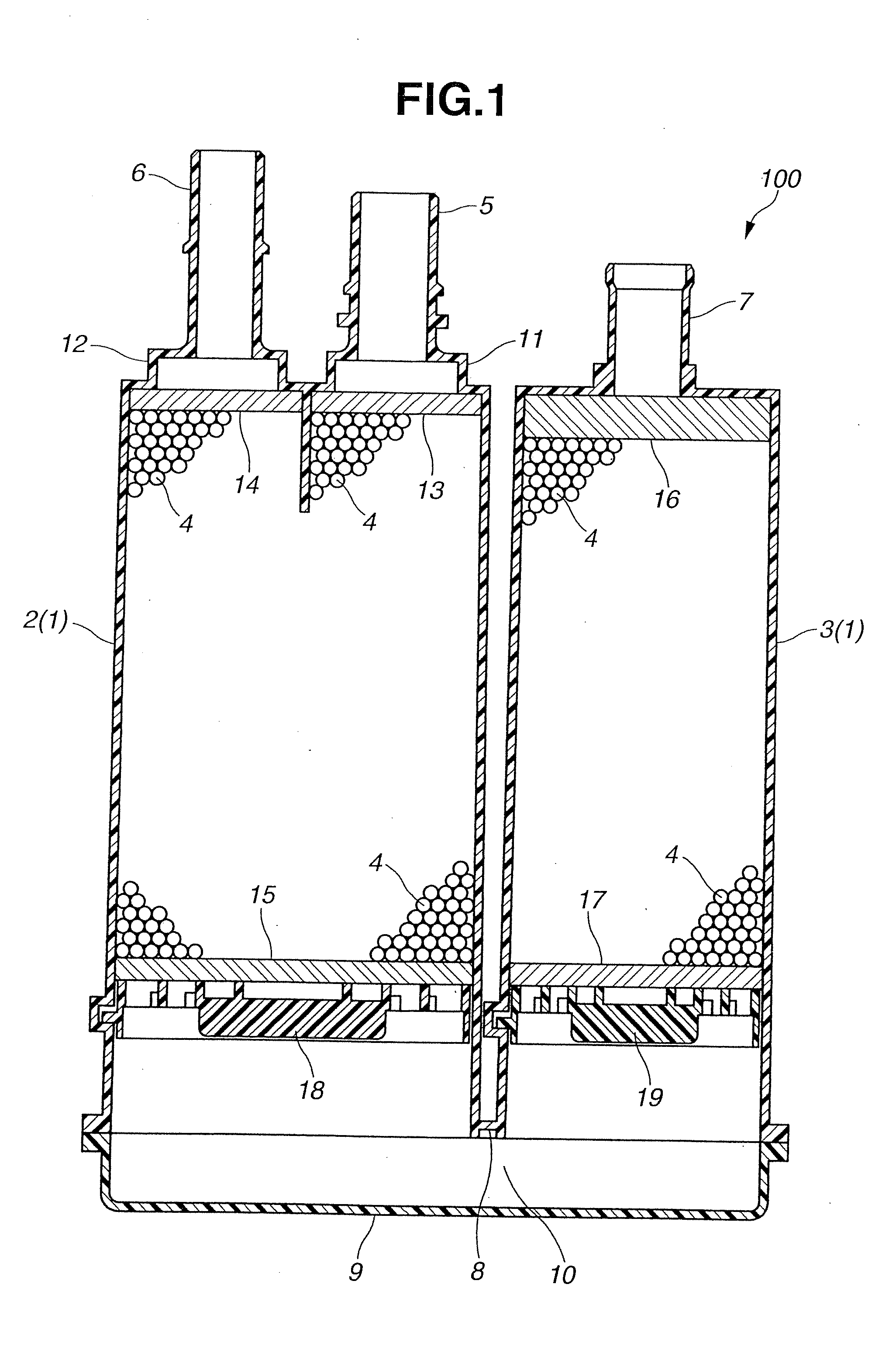
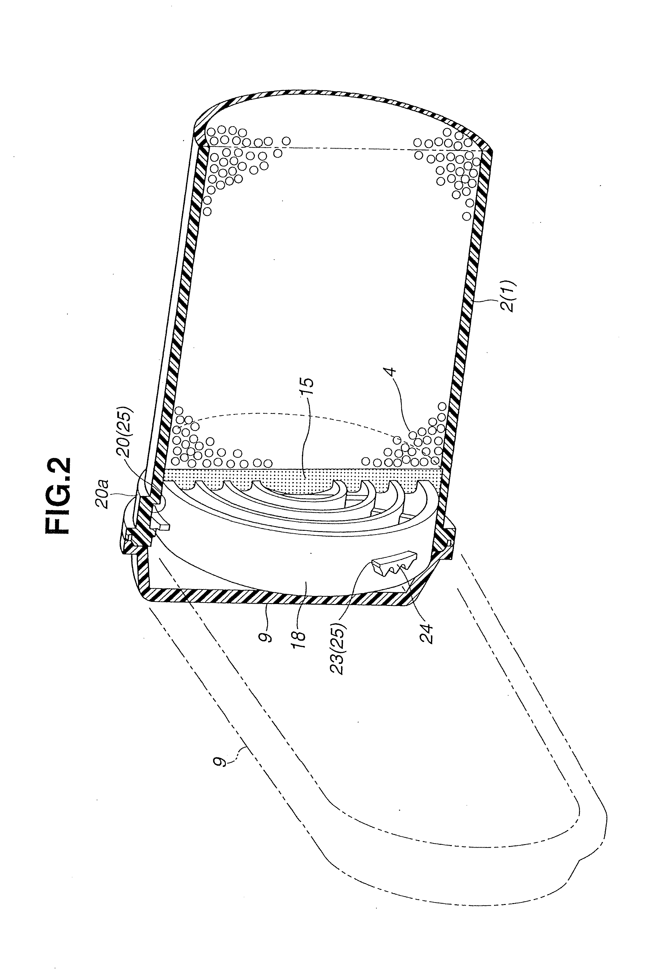
[0035]Referring to FIG. 1 to FIG. 5, an evaporated fuel treatment device (hereinafter referred to simply as a canister) according to the present invention will be explained hereinafter. FIG. 1 shows a section of a so-called dual chamber canister as a whole. FIG. 2 to FIG. 5 show a construction of details of the canister shown in FIG. 1.

[0036]As shown in FIG. 1, a canister 100 includes a hermetically sealed casing 1, and an adsorbent 4 filled in the casing 1. The adsorbent 4 is granular activated carbon. The granular activated carbon may be generally in the form of granulated carbon particles or crushed carbon particles. The casing 1 includes a charge port 5, a purge port 6, an atmospheric vent port 7 and a cover member 9. The cover member 9 is disposed at one end of the casing 1. The charge port 5, the purge port 6 and the atmospheric vent port 7 are disposed at the other end of the casing 1.

[0037]Specifically, the casing 1 includes two cylindrical casing bodies 2, 3 made of a prede...

third embodiment

[0076]Upon assembling the canister 300 the retainer member 34 is simply pushed into the casing body 2 without being rotated. When the air permeable member 15 is brought into an appropriately compressively deformed state through the retainer member 34, the pushing force applied to the retainer member 34 is released to thereby allow meshing engagement between the tooth-shaped projecting portion 30 and the grooves and the tooth-shaped projecting portion 31. With the meshing engagement between the tooth-shaped projecting portion 30 and the tooth-shaped projecting portion 31, the retainer member 34 can be placed and held in a stepwise optional position in a direction of the pushing force. As a result, the retainer member 34 can be prevented from being removed from the casing body 2, and the air permeable member 15 can be kept in the appropriately compressively deformed state.

[0077]Accordingly, the canister 300 according to the third embodiment can attain the same effects as those of the...


PUM


Abstract

An evaporated fuel treatment device including a cylindrical casing body, a granular adsorbent filled in the casing body, an air permeable member stacked on the granular adsorbent, a retainer member stacked on the air permeable member, and a tJooth-shaped positioning retention mechanism disposed between an inner circumferential surface of the casing body and an outer circumferential surface of the retainer member. The tooth-shaped positioning retention mechanism allows the retainer member to hold the air permeable member in a compressively deformed state, enables positioning and retention of the retainer member in an optional position relative to the casing body in a pushing direction of the retainer member, and inhibits displacement of the retainer member in a removal direction of the retainer member.

Description

BACKGROUND OF THE INVENTION[0001]The present invention relates to an evaporated fuel treatment device (also referred to as a canister) that is used for adsorbing fuel evaporated in a fuel tank of an automobile in order to allow combustion of the fuel in an engine during operation of the engine.[0002]For example, a so-called carbon canister using activated carbon as an adsorbent is known as a conventional evaporated fuel treatment device. The canister has a flow path therein through which evaporated fuel and atmospheric air are allowed to flow. The evaporated fuel generated from the fuel tank is temporarily adsorbed in the activated carbon in the canister. On the other hand, during an operation of an engine, atmospheric air is introduced into the canister using an engine negative pressure, and the evaporated fuel adsorbed in the activated carbon is desorbed therefrom. The evaporated fuel thus desorbed is sucked into the engine, thereby serving for combustion of the evaporated fuel.[0...

Claims


Application Information

Patent Timeline
Patent Type & Authority Applications(United States)
IPC IPC(8): F02M25/08
CPCF02M25/0854B01D53/0415B01D2259/4516
Inventor ARASE, YUJIYOSHIDA, HIROYUKIHORIMATSU, TOSHINOBU
Owner MAHLE FILTER SYST JAPAN CORP
Why Eureka
Try Eureka