
Spacercraft Shield

a shield and spacecraft technology, applied in the field of shields, can solve the problems of spacecrafts being bombarded with space debris, shells more susceptible to subsequent failure, and loss of a habitable pressurized environmen

Active Publication Date: 2013-12-12
BIGELOW AEROSPACE
View PDF27 Cites 6 Cited by
  • Summary
  • Abstract
  • Description
  • Claims
  • Application Information

AI Technical Summary

Benefits of technology

The patent is about a method for creating a protective shield for spacecraft to protect against space debris. The shield is made by growing carbon nanotubes in a low gravity environment and is attached to the outer surface of the spacecraft. Multiple shields can be used to cover the entire surface of the spacecraft. The technical effect is better protection against space debris for spacecraft.

Problems solved by technology

Missions in space face the problem of spacecrafts being bombarded with space debris including meteoroids ranging in size from microscopic particles to visibly larger compositions.
Some high velocity debris can penetrate a traditional hard shelled spacecraft or cause a great deal of impact damage that weakens the shell of the craft making the shell more susceptible to subsequent failure.
In the case of a penetration of the hull, this can lead to loss of a habitable pressurized environment that can endanger a crew.
The debris could also impact sensitive equipment in a spacecraft, which could cause a variety of failures.
Naturally, a solid metal shield—like steel—would be very heavy for a large spacecraft and that translates into a great deal of expense to place such a shield into orbit.

Method used


Image

  • Spacercraft Shield
  • Spacercraft Shield
  • Spacercraft Shield

Examples


Embodiment Construction

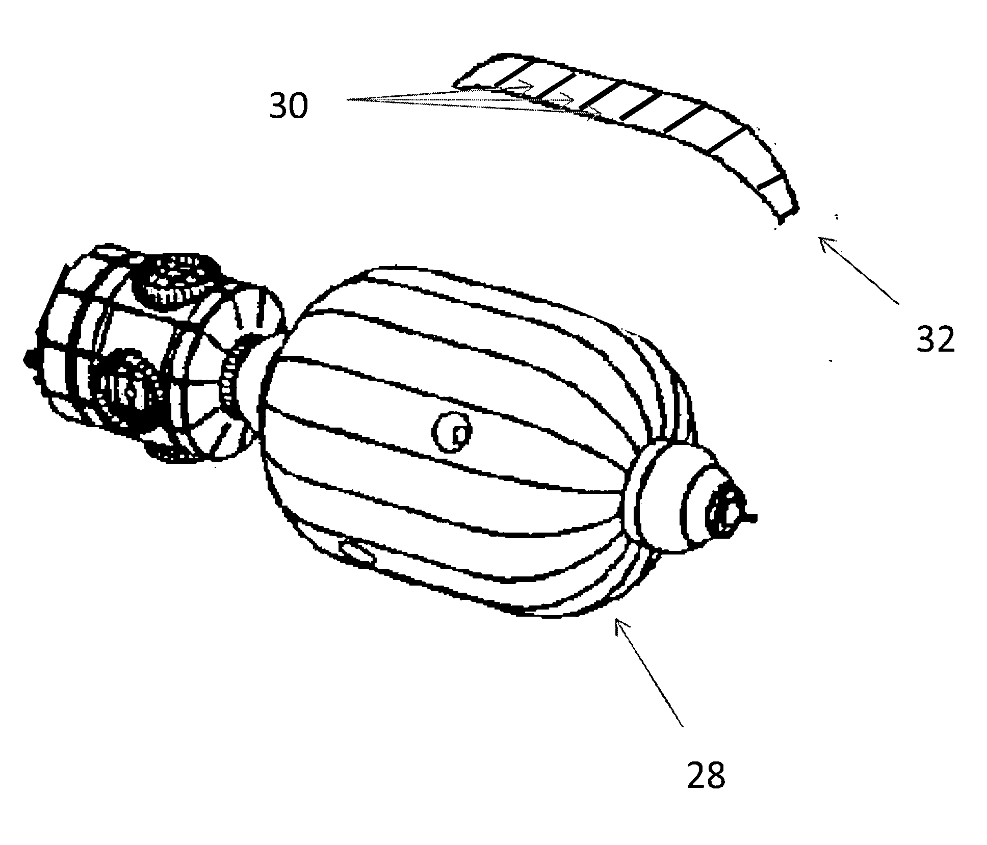
[0017]One aspect of the present invention is the use of carbon nanotubes (CNTs) as a bumper in a spacecraft shield for a Whipple type configuration. CNTs are cylindrical in shape and can have a length-to-diameter ration of up to approximately 132,000,000:1.

[0018]CNTs also have a strength between 10-60 GPa (gigapascals), which is much higher than steel. Even so, the specific density of CNTs is between 1.3-2 while steel is 7.8 making CTNs attractive for space deployment. CNTs can take numerous shapes such as single walled or multi-walled.

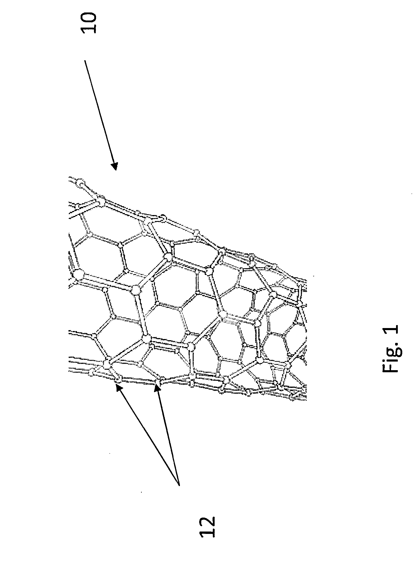
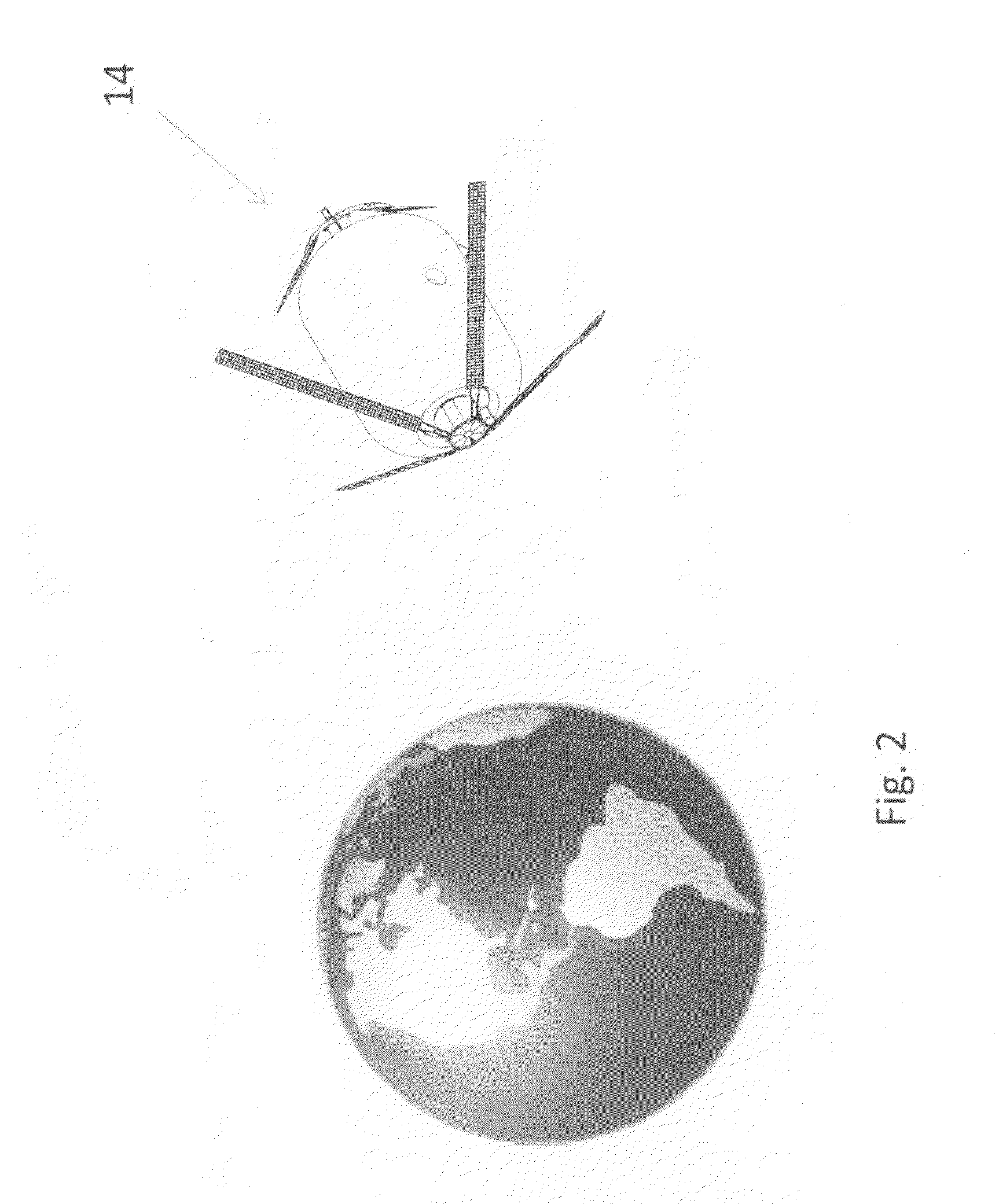
[0019]FIG. 1 identifies the general structure of a CNT 10, which is comprised of carbon atoms 12 bonded together. FIG. 2 identifies a space deployed facility 14 for producing carbon nanotubes. The facility 14 can be a spacecraft suitable for human habitation. In the embodiment identified, the facility 14 is an inflatable spacecraft for human use. In this figure, the spacecraft 14 is in orbit about the Earth.

[0020]The carbon nanotubes can be grown by t...


PUM


Abstract

A spacecraft carbon nanotube shield is disclosed. Shield segments are produced in a facility in space. The segments are transported from the facility to a vicinity of a spacecraft hull. The segments are assembled over the hull to substantially cover an area of the hull.

Description

FIELD OF THE INVENTION[0001]This invention generally relates to shields for use with a deployed spacecraft. In particular, this application addresses the use of carbon nanotubes in a spacecraft shield configuration.BACKGROUND OF THE INVENTION[0002]Missions in space face the problem of spacecrafts being bombarded with space debris including meteoroids ranging in size from microscopic particles to visibly larger compositions. Compounding this problem is the case where the debris is traveling at high velocities.[0003]Some high velocity debris can penetrate a traditional hard shelled spacecraft or cause a great deal of impact damage that weakens the shell of the craft making the shell more susceptible to subsequent failure. In the case of a penetration of the hull, this can lead to loss of a habitable pressurized environment that can endanger a crew. The debris could also impact sensitive equipment in a spacecraft, which could cause a variety of failures.[0004]One solution to this probl...

Claims


Application Information

Patent Timeline
Patent Type & Authority Applications(United States)
IPC IPC(8): B64G1/56B82B3/00B82Y30/00
CPCB64G1/56B82Y30/00B82Y40/00Y10S977/742Y10S977/842Y10S977/902
Inventor BIGELOW, ROBERT T.
Owner BIGELOW AEROSPACE
Learn More