Rotorcraft yaw piloting system making use of a member of the human-operated type and of a flight control generator fo the objective type

a technology of rotary wings and rudders, which is applied in the direction of vehicle position/course/altitude control, process and machine control, instruments, etc., can solve the problems of affecting the pertinence, and affecting the accuracy of yaw piloting. , to achieve the effect of improving the interfa

Inactive Publication Date: 2013-12-12
EUROCOPTER
View PDF8 Cites 10 Cited by
  • Summary
  • Abstract
  • Description
  • Claims
  • Application Information

AI Technical Summary

Benefits of technology

[0034]The object of the present invention is to provide a yaw flight control system for a rotorcraft and a method making use of the system that improves the interface between the human pilot and the yaw flight control system in order to remedy the drawbacks mentioned above.

Problems solved by technology

For rotorcraft, it is sometimes found in practice that there are drawbacks relating to yaw piloting via the rudder bar.
Clearances and inaccuracies in the movement of the moving mechanical members making up the mechanical drive channel are inevitable, to the detriment of the “feel” perceived by the human pilot and to the detriment of the pertinence of the flight commands transmitted to the anti-torque rotor.
It is also observed in automatic piloting mode that the human pilot may act unintentionally on the rudder bar, e.g. because the pilot may take up a poor posture in the cockpit and / or because it is difficult for the human pilot to sense small movements of the rudder bar through feet wearing boots used by the human pilot to move the pedals of the rudder bar.
The human pilot may unintentionally oppose the action of the actuators on the drive channel, such as movement of the trim actuator used for recentering the series actuator.
The series actuator may become saturated, thereby leading to a loss of stabilization of the rotorcraft.

Method used


Image

  • Rotorcraft yaw piloting system making use of a member of the human-operated type and of a flight control generator fo the objective type
  • Rotorcraft yaw piloting system making use of a member of the human-operated type and of a flight control generator fo the objective type

Examples


Embodiment Construction

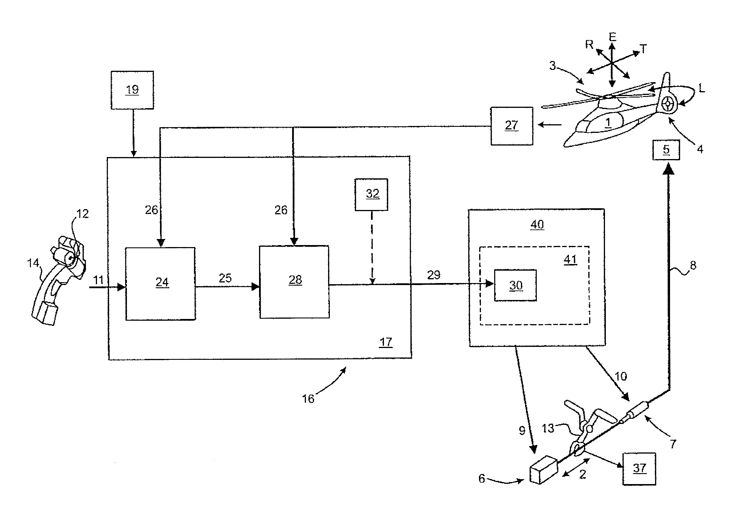
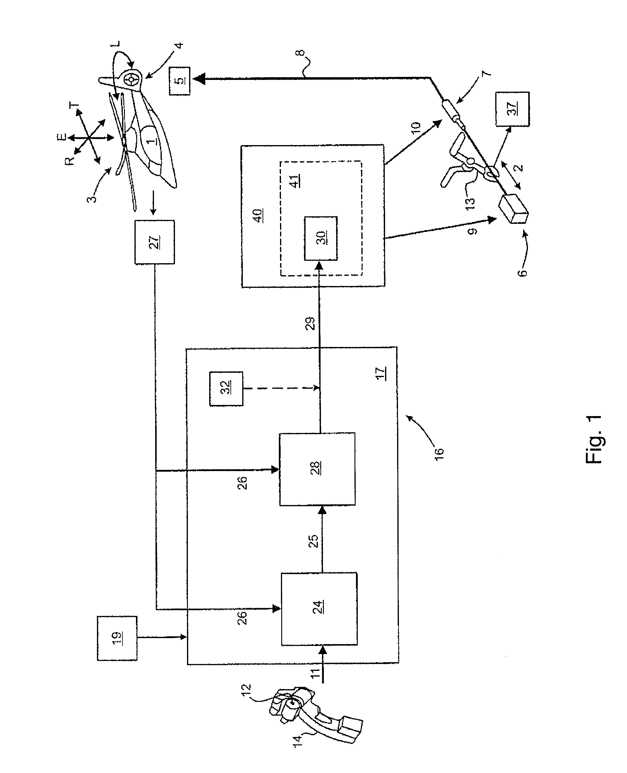
[0079]In FIG. 1, a rotorcraft 1 has a main rotor 3 and an anti-torque tail rotor 4, each comprising a rotary wing having blades. A pilot of the rotorcraft can control the blades of the main rotor 3 in order to change the state of progression of the rotorcraft 1 relative to corresponding flight orientations, in particular in pitching P, in roll R, and in elevation E. By controlling the blades of the tail rotor 4, the pilot changes the state of progression of the rotorcraft 1 in yaw Y. The pilot of the rotorcraft may be a human pilot or an autopilot.

[0080]The pitch of the blades of the tail rotor 4 is varied by means of a servo-control 5 by using a yaw flight control system forming part of the rotorcraft 1. The servo-control 5 is placed on a mechanism 8 for transmitting mechanical forces. Operation of the mechanical transmission mechanism 8 depends on a set of pedals of a rudder bar 13 and on actuators 6 and 7. Such actuators are constituted in particular by a trim actuator 6 that is ...


PUM


Abstract

A system and a method for controlling a rotorcraft (1) in yaw (Y). The control system comprises a plurality of drive channels that operate an anti-torque rotor (4) of the rotorcraft (1). A first drive channel makes use of a rudder bar (13) including a set of pedals operated by the human pilot of the rotorcraft in order to control the anti-torque rotor (4). A second drive channel includes an autopilot. A third drive channel includes objective-type flight control means comprising a movable control member (12) that is operated by the human pilot and that continuously issues control signals (11) relating to a state of progression that the rotorcraft (1) is to achieve. Use of the second drive channel and of the third drive channel depends on inhibit means (19) for inhibiting operation thereof, which means are activatable by detector means (37) for detecting operation of the rudder bar (13).

Description

CROSS REFERENCE TO RELATED APPLICATIONS[0001]This application claims priority to French patent application No. FR 11 03067 filed on Oct. 10, 2011, the disclosure of which is incorporated in its entirety by reference herein.BACKGROUND OF THE INVENTION[0002](1) Field of the Invention[0003]The present invention relates to the field of rotary-wing aircraft, and more particularly to control systems for directional piloting in yaw of a rotorcraft, in particular of a helicopter.[0004]The invention provides a yaw flight control system for a rotorcraft that makes use of at least one member of the type operated by a human, in particular a human pilot of the rotorcraft, and of calculation means that operate actuators for acting on an anti-torque rotor of the rotorcraft.[0005](2) Description of Related Art[0006]Rotorcraft are fitted with rotors, each constituting a rotary wing made up of a plurality of blades, which blades extend radially around a rotary drive axis of the rotary wing. A main ro...

Claims


Application Information

Patent Timeline
Patent Type & Authority Applications(United States)
IPC IPC(8): B64C27/78
CPCB64C27/78G05D1/0858B64C13/22
Inventor MEZAN, SERGE
Owner EUROCOPTER
Why Eureka
Try Eureka