Quick release devices

a quick release device and quick release technology, which is applied in the direction of rolling resistance optimization, hubs, vehicle components, etc., can solve the problems of reducing increasing the manufacturing cost and total weight, etc., and achieves the reduction of the length of the movable shaft, the manufacturing cost and weight and the service life of the quick release device.

Active Publication Date: 2013-12-12
APROTECH
View PDF3 Cites 20 Cited by
  • Summary
  • Abstract
  • Description
  • Claims
  • Application Information

AI Technical Summary

Benefits of technology

[0016]In the pressing state, since only the pressing members are in contact with the bicycle frame, a pressure exerted on the bicycle frame is relative uniform so that wear occurred between the quick release device and the bicycle frame is reduced to prolong

Problems solved by technology

When used for a long time period, or when frequent assembly and disassembly occur, the front fork 11 and the axle tube 12 experience serious wear

Method used


Image

  • Quick release devices
  • Quick release devices
  • Quick release devices

Examples


Embodiment Construction

[0027]Before the present invention is described in greater detail in connection with the preferred embodiments, it should be noted that similar elements and structures are designated by like reference numerals throughout the entire disclosure.

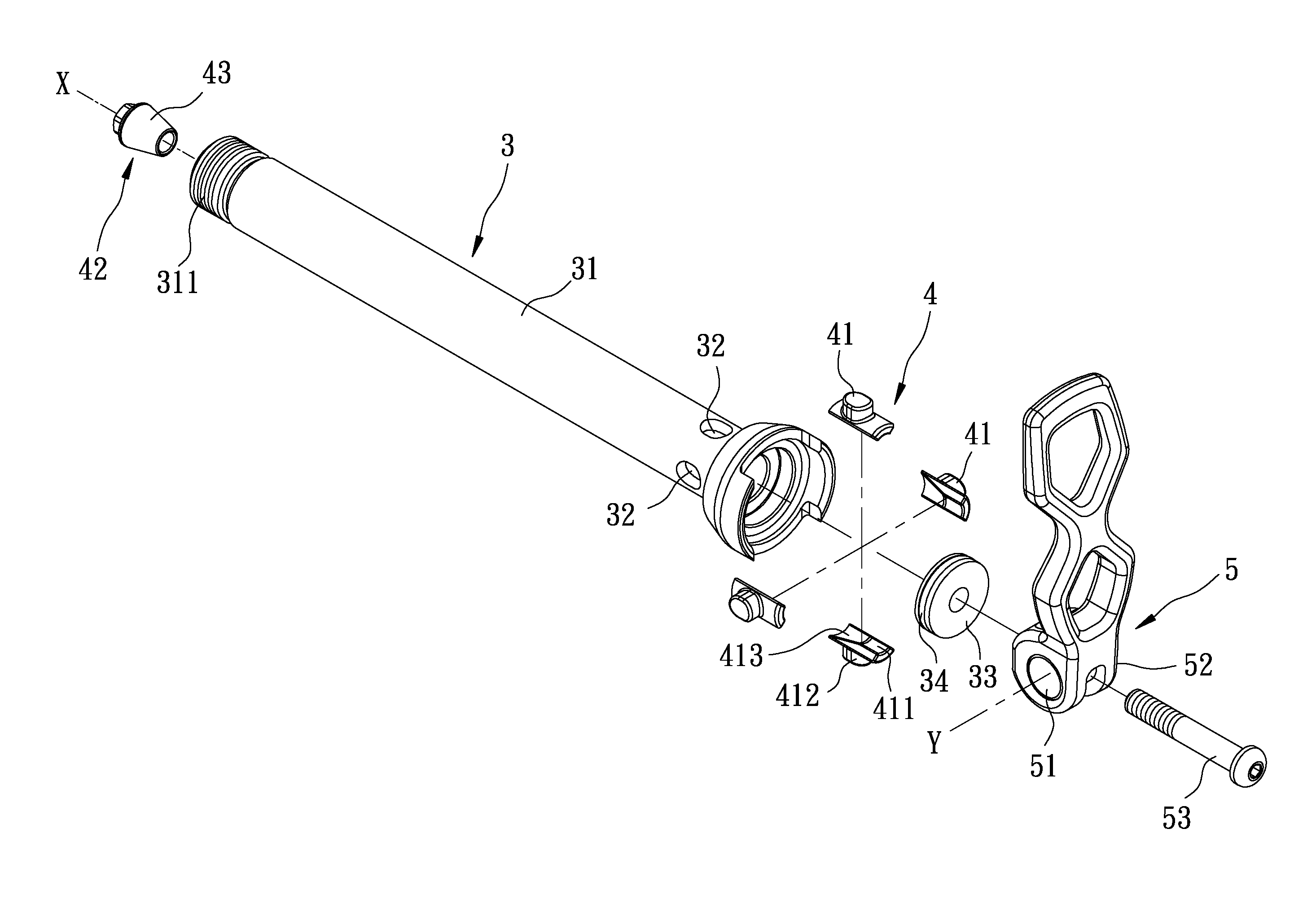
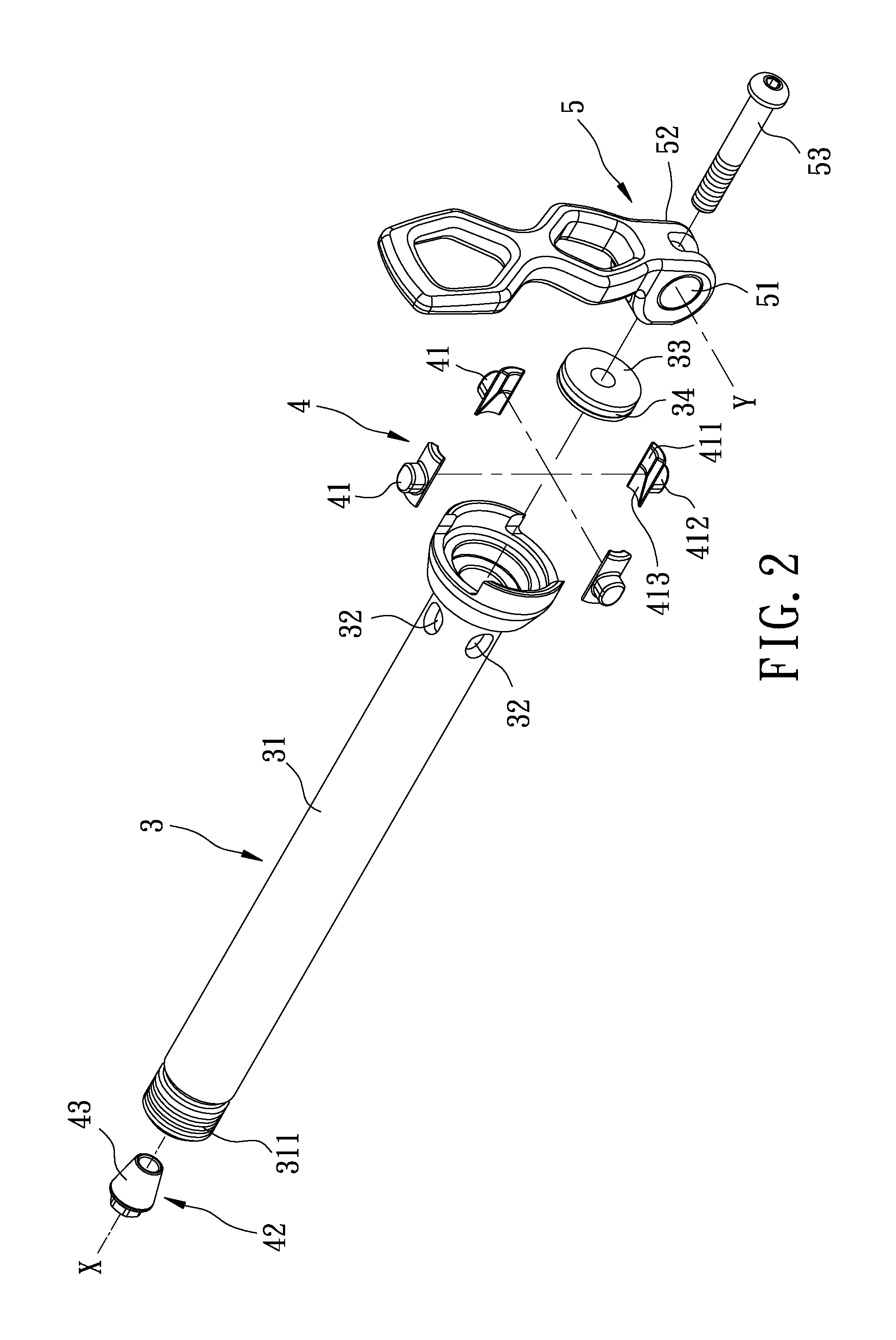
[0028]Referring to FIGS. 2, 3, and 4, the first preferred embodiment of a quick release device according to this invention is adapted to be mounted to a part of a bicycle frame 2, such as a front fork, and includes an axle tube unit 3, a pressing unit 4, and a driving unit 5.

[0029]The axle tube unit 3 extends along a horizontal axis (X) and through the bicycle frame 2, and includes an axle tube 31, a plurality of through holes 32 formed through a tube wall of the axle tube 31 and disposed around the axis (X), a support seat 33 disposed within an end of the axle tube 31 proximate to the driving unit 5, and a seal ring 34 disposed between the axle tube 31 and the support seat 33. A left end 311 of the axle tube 31 is threaded within the bicycle f...


PUM


Abstract

A quick release device includes an axle tube, a pressing unit, and a driving unit. The axle tube extends through a bicycle frame, and has a plurality of through holes. The pressing unit includes a plurality of pressing members disposed respectively and movably within the through holes in the axle tube, and a pushing member movable axially in the axle tube. The driving unit includes a movable shaft. When the driving unit is changed to a locking state, the movable shaft moves the pushing member such that the pushing member pushes and moves the pressing member to press against the bicycle frame. When the driving unit is changed to a release state, the movable shaft moves the pushing member away from the pressing members to allow the pressing members to move radially away from the bicycle frame.

Description

CROSS-REFERENCE TO RELATED APPLICATION[0001]This application claims priority of Taiwanese Application No. 101120681, filed on Jun. 8, 2012.BACKGROUND OF THE INVENTION[0002]1. Field of the Invention[0003]This invention relates to a part of a bicycle, and more particularly to a quick release device.[0004]2. Description of the Related Art[0005]Referring to FIG. 1, a conventional quick release device is mounted to a front fork 11 of a bicycle, and includes an axle tube 12, left and right pushing blocks 13, 13′, a driving unit 14, a rotary lever 15, and a movable shaft 16.[0006]The axle tube 12 extends through the front fork 11, and includes a tube wall 122 disposed around and extending along an axis 121 and having two deformable sections 123 disposed respectively at two opposite ends of the tube wall 122. Each of the deformable sections 123 has a frustoconical inner wall surface 124, and a plurality of open-ended slots 125 parallel to the axis 121 and formed through the tube wall 122.[0...

Claims


Application Information

Patent Timeline
IPC IPC(8): B60B27/02B60B35/00
CPCB60B27/026B60B35/004B60B2900/112B60B2900/111Y02T10/86
Inventor KUO, CHIH-PING
Owner APROTECH
Why Eureka
Try Eureka