Video camera positioning system and control method thereof

a positioning system and video camera technology, applied in the field of photography, can solve the problems of time-wasting and complicated above-mentioned operation

Inactive Publication Date: 2013-12-12
AVER INFORMATION INC
View PDF3 Cites 26 Cited by
  • Summary
  • Abstract
  • Description
  • Claims
  • Application Information

AI Technical Summary

Benefits of technology

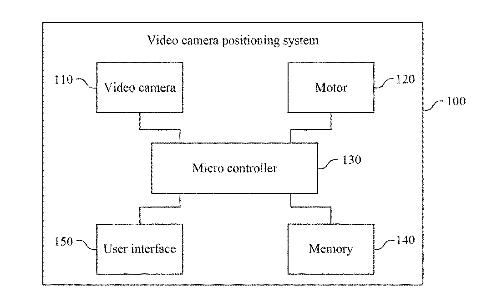
[0006]A video camera positioning system and a method for controlling thereof are provided, ...

Problems solved by technology

The above-mentioned operatio...

Method used


Image

  • Video camera positioning system and control method thereof
  • Video camera positioning system and control method thereof
  • Video camera positioning system and control method thereof

Examples


Embodiment Construction

[0028]The present disclosure is more particularly described in the following examples that are intended as illustrative only since numerous modifications and variations therein will be apparent to those skilled in the art. Various embodiments of the disclosure are now described in detail. Referring to the drawings, like numbers indicate like components throughout the views. As used in the description herein and throughout the claims that follow, the meaning of “a,”“an,” and “the” includes plural reference unless the context clearly dictates otherwise. Also, as used in the description herein and throughout the claims that follow, the meaning of “in” includes “in” and “on” unless the context clearly dictates otherwise.

[0029]The terms used in this specification generally have their ordinary meanings in the art, within the context of the disclosure, and in the specific context where each term is used. Certain terms that are used to describe the disclosure are discussed below, or elsewhe...


PUM


Abstract

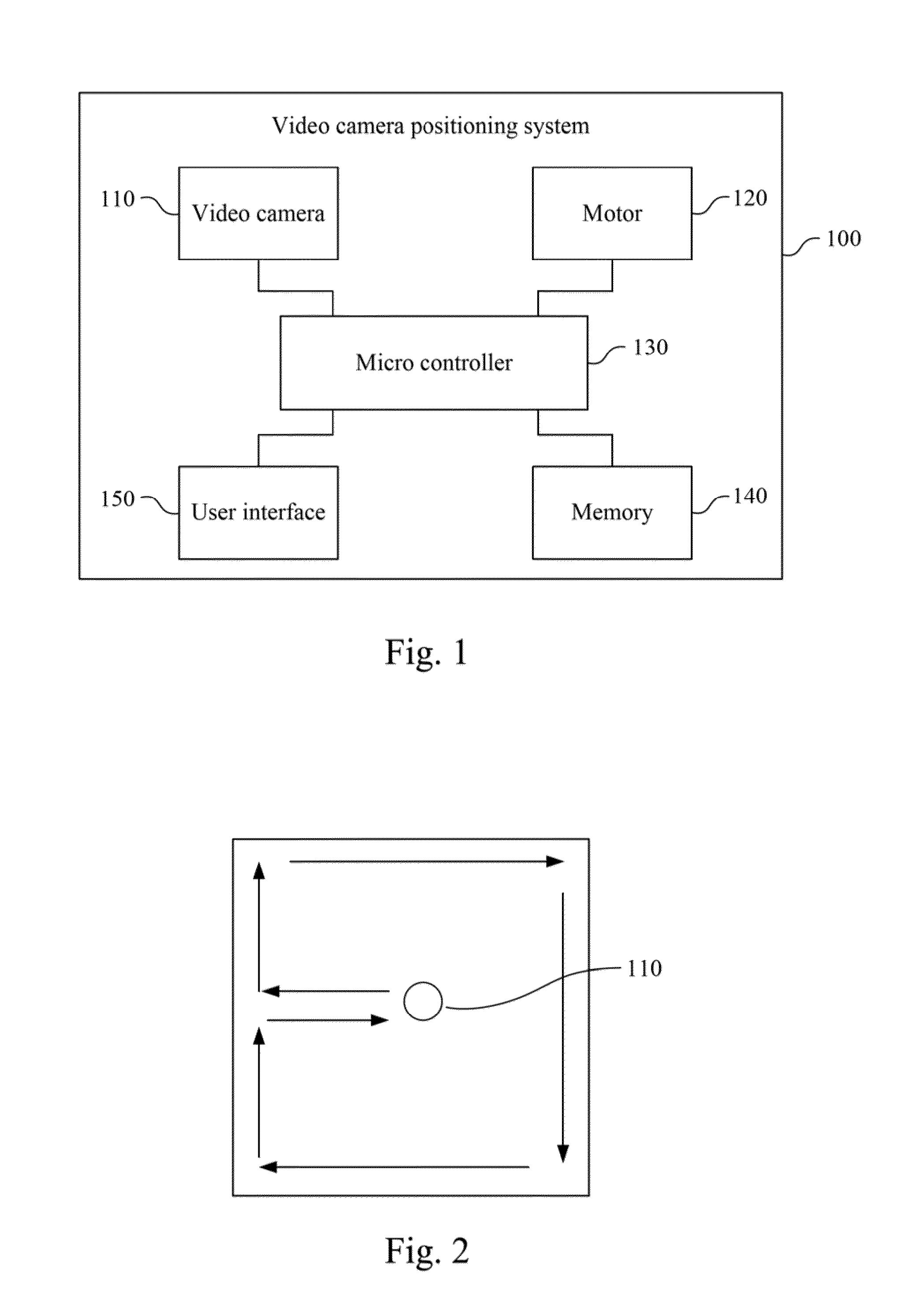
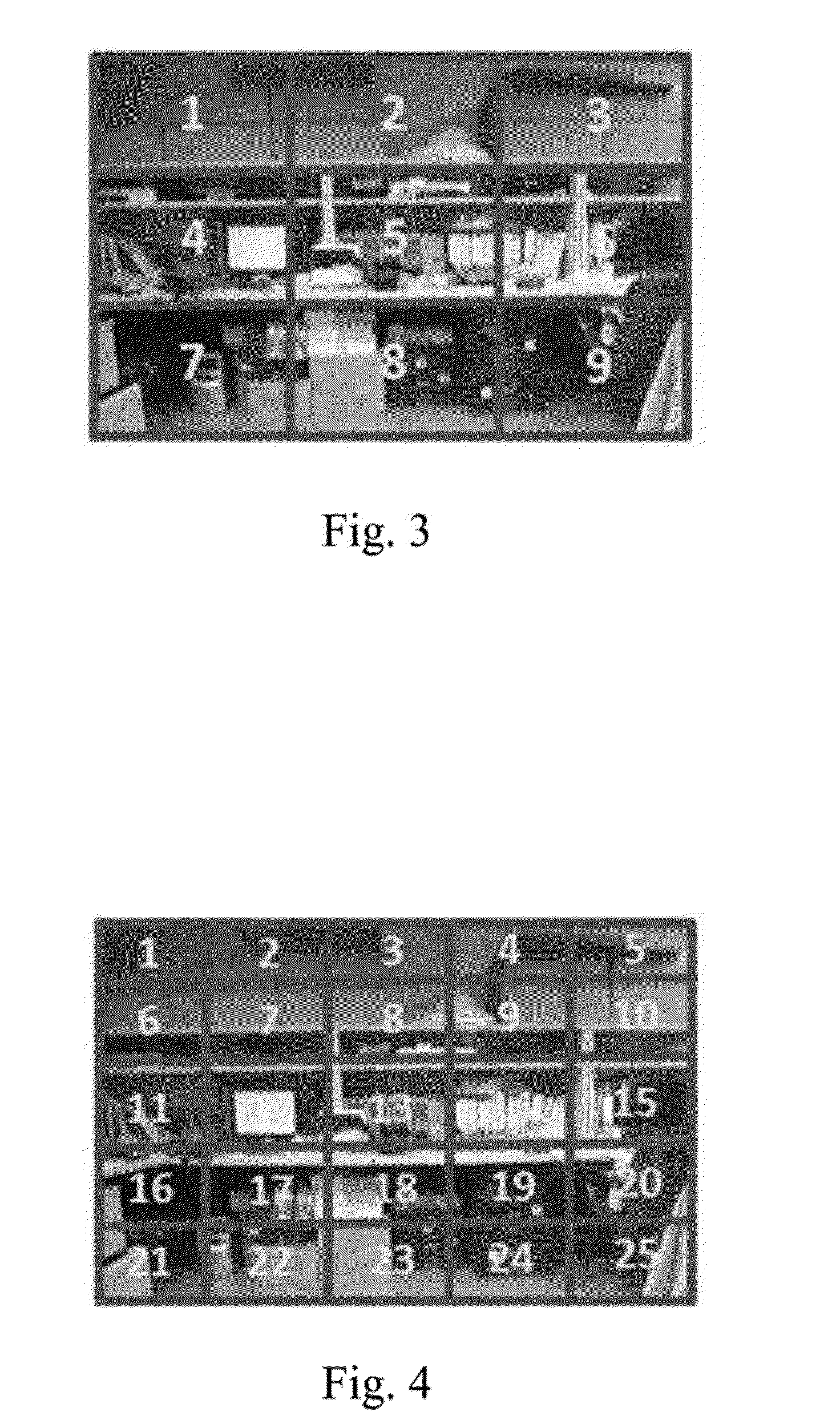
A method for controlling a video camera positioning system includes the steps of controlling a motor for driving a video camera to capture a panoramic frame, dividing the panoramic frame into a plurality of frames, controlling the motor for driving the camera lens to turn to the frame corresponding to an encoded command signal when the microcontroller receiving the encoded command signal, and zooming in the frame by the video camera. Furthermore, a video camera positioning system is also disclosed herein.

Description

BACKGROUND[0001]1. Technical Field Disclosure[0002]The embodiment of the present disclosure relates generally to photography and, more particularly, to a video camera positioning system and a method for controlling thereof.[0003]2. Description of Related Art[0004]Positioning a video camera is required in using an IP camera, a web cam or a videoconference system. When a user needs to locate an area inside (or outside) a frame or zoom in an area, a remote control is required to drive the video camera to slowly turn to the area which is needed to be zoomed in. The above-mentioned operation is time-wasting and complicated.[0005]Many efforts have been devoted trying to find a solution of the aforementioned problems. Nonetheless, there still a need to improve the existing apparatus and techniques in the art. Therefore, it is an important subject and also a purpose in need of improvement that how to solve the problem of a conventional positioning mode being time-wasting and complicated.SUM...

Claims


Application Information

Patent Timeline
IPC IPC(8): H04N5/262H04N7/00
CPCH04N5/23296H04N5/23238H04N23/698H04N23/69
Inventor HSIA, MING-HUNGHSU, YING-FENGHUNG, HUI-LUNWANG, YO-JUNG
Owner AVER INFORMATION INC
Why Eureka
Try Eureka