Quick assembly and disassembly mechanism with button lock for a toilet cover

Active Publication Date: 2013-12-19
XIAMEN R&T PLUMBING TECH
View PDF6 Cites 8 Cited by
  • Summary
  • Abstract
  • Description
  • Claims
  • Application Information

AI Technical Summary

Benefits of technology

[0023]The advantageous effects of the present invention are as below: only one end of the lock bar is travel self-locked in the lock catch in one end of the straight tube, making the pins unlocked to the lock holes in two ends of the lock bar, making the pivot shaft and the pin separable

Problems solved by technology

So the reliab

Method used


Image

  • Quick assembly and disassembly mechanism with button lock for a toilet cover
  • Quick assembly and disassembly mechanism with button lock for a toilet cover
  • Quick assembly and disassembly mechanism with button lock for a toilet cover

Examples


Example

The First Embodiment (Push Type to Drive the Lock Bar to Move)

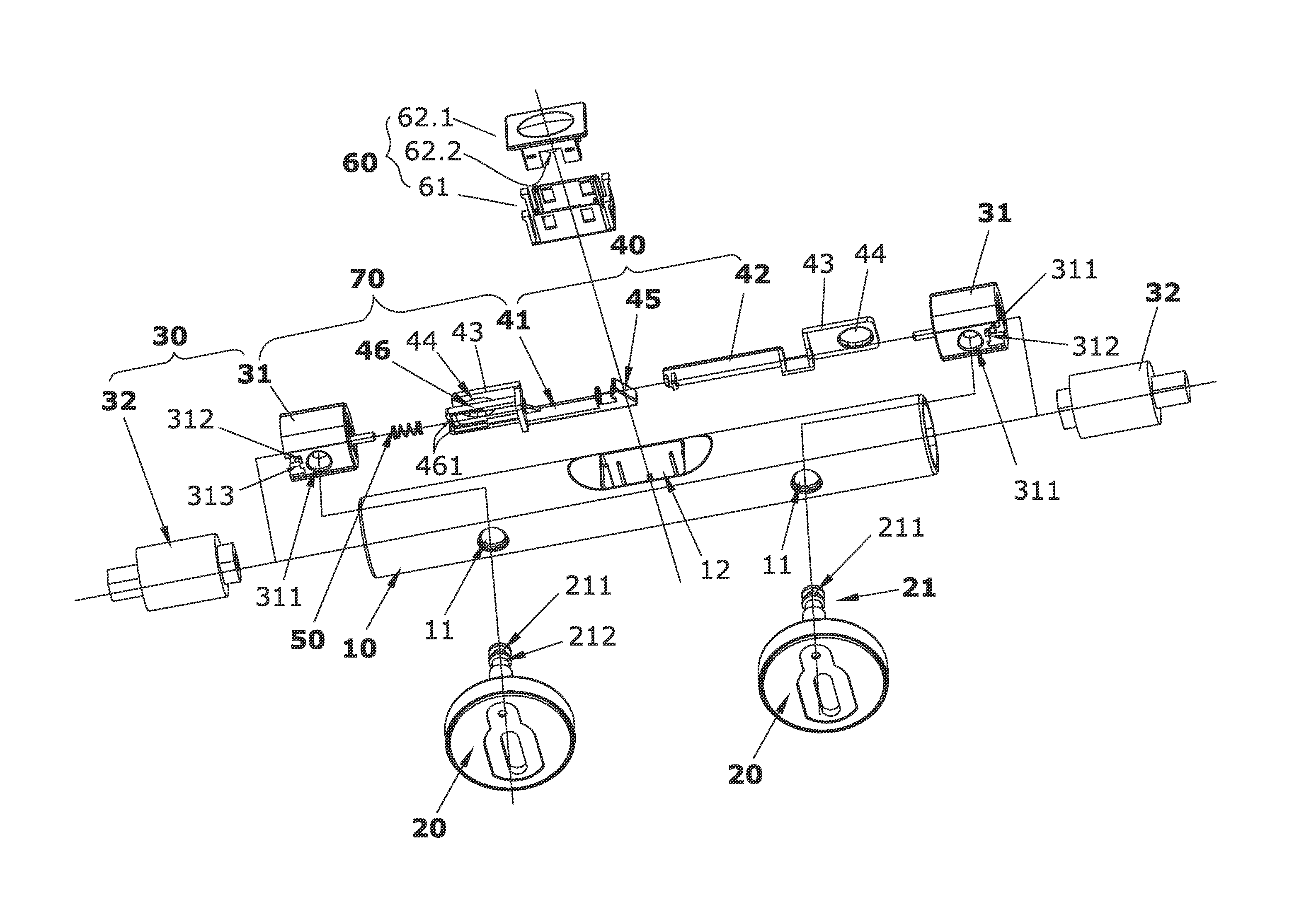
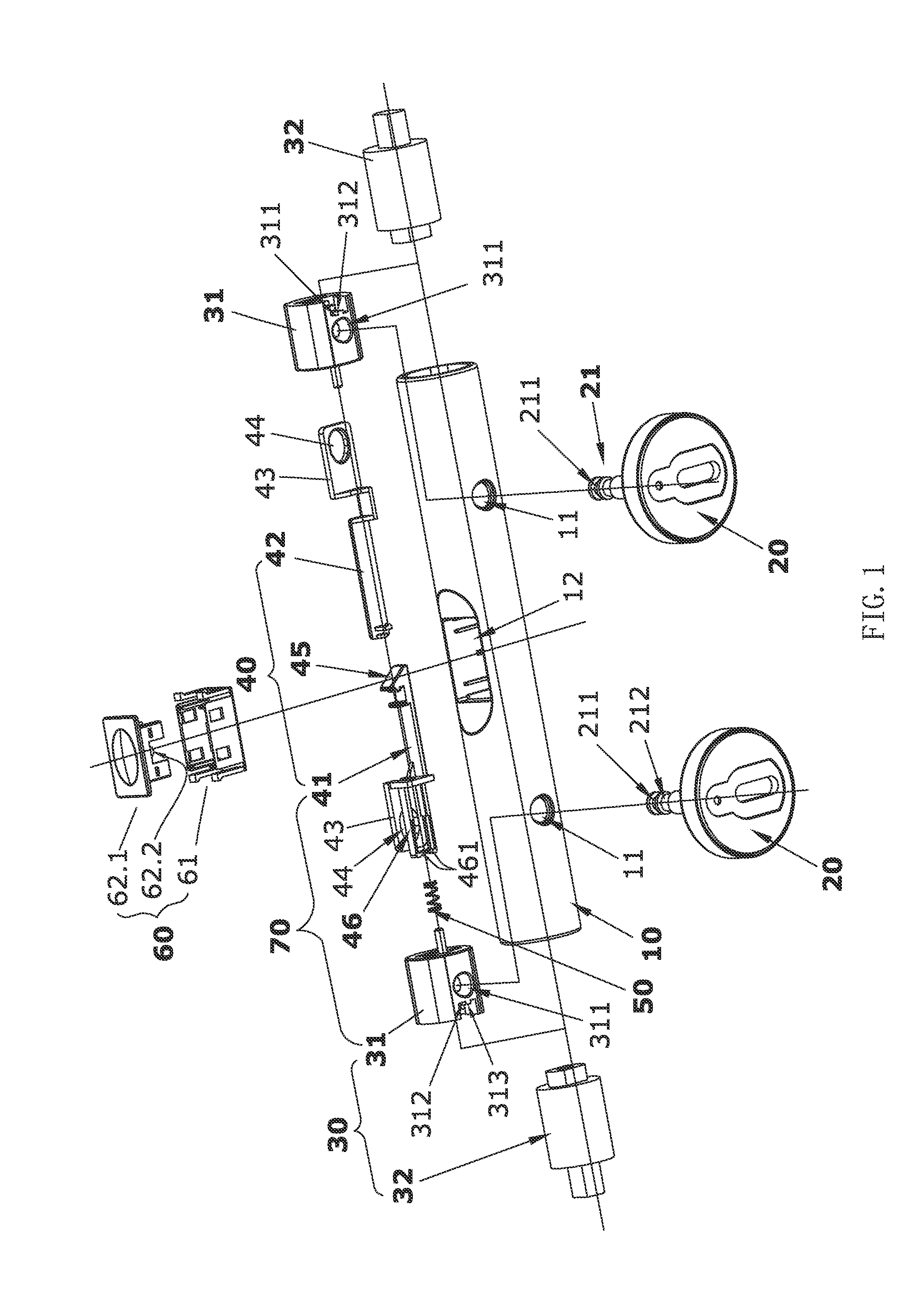
[0042]As shown in FIG. 1 to FIG. 6. A quick assembly and disassembly mechanism with button lock for a toilet cover comprising an independent circular straight tube 10 pivot joint to middle of the rear part of the cover and two stands 20 to connect to the toilet, two pivot shafts 30 plugged to the shaft holes of the cover are symmetrically fixed to two ends of the straight tube 10, each pivot shaft 30 comprising a standstill shaft 31 and a rotary damper 32 coaxially, the standstill shaft 31 and the rotary damper 32 are sleeved into the straight tube 10, the rotary damper 32 is extended out of the end of the straight tube 10, the standstill shaft 31 is disposed with a pin hole 311 in the radial direction, the pin hole 311 is corresponding to the radial hole 11 of the straight tube 10 and it is plugged with the pin 21 of the stand 20; a lock bar 40 is disposed inside the straight tube 10 and between the two standstill shaft ...

Example

The Second Embodiment (Gear Type to Drive the Lock Bar to Move)

[0046]As shown in FIG. 15, the difference from the first embodiment is as below: replace the button 62.1 in the operation mechanism 60 in the first embodiment by a gear 63 assemble in the base 61, replace the guiding block 45 of the left lock bar 41 of the lock bar 40 by a rack 47, the gear 63 is engaged to the rack 47, rotate the gear 63 to drive the rack 47 to move, making the lock bar 40 sliding left and the lock bar 40 locked to the unlock surface 313 of the standstill shaft 31 in the left by the inner hook 461 of the left lock bar 41, then the moving travel of the lock bar 40 in the lock catch 70 in the left end of the straight tube 10 is self-locked, when the lock catch 70 is unlocked, the lock bar 40 is repositioned with the effect of the spring force, the rack 47 drives the gear 63 to rotate in the opposite direction and reposition. The other structure, work principle and implementation means of the second embodi...

Example

The Third Embodiment (Lever Type Balance Button to Drive the Lock Bar to Move)

[0047]As shown in FIG. 16, the difference from the first embodiment is as below: replace the button 62.1 of the operation mechanism in the first embodiment by a lever type balance button 64 assembled in the base 61, a shifting lever 64.1 is disposed at the bottom of the balance button 64, replace the guiding block 45 of the left lock bar 41 by a pushing block 48, press the balance button 64 to make the shifting lever 64.1 driving the pushing block 48 to drive the lock bar 40 to move; the other structure, work principle and implementation means of the second embodiment is similar to the first embodiment.

[0048]Although the present invention has been described with reference to the preferred embodiments thereof for carrying out the patent for invention, it is apparent to those skilled in the art that a variety of modifications and changes may be made without departing from the scope of the patent for inventio...


PUM


Abstract

A quick assembly and disassembly mechanism with a button lock for a toilet cover has a straight tube pivot joint, two stands and two pivot shafts. Each pivot shaft is disposed with pin holes in the radial direction. A lock bar disposed between the pivot shafts can slide side to side. The straight tube is disposed with an operation mechanism to drive the lock bar to slide. A spring is disposed inside the straight tube to reposition the lock bar. The lock bar is disposed with a lock catch and a lock piece with lock hole. The lock catch has an elastic body and a lock piece to limit the sliding of the lock bar and a pivot shaft, which is plugged to the end of the lock bar in sliding way. The lock piece in the end of the lock bar is disposed with a lock hole.

Description

DESCRIPTION[0001]1. Field of the Invention[0002]The present invention relates to an assembly mechanism of a toilet cover, especially to a quick assembly and disassembly mechanism with button lock for a toilet cover.[0003]2. Background of the Invention[0004]The existing quick pivot device of the cover and the toilet is applied with a lock shaft assembly stand, for example, a button type quick lock switch is separately assembled in the left and the right part of the rear part of the cover. The Chinese utility model patent with publication number CN201767898U is provided with a hinge structure of a toilet cover, which comprising a cover connected to the toilet with a hinge, the hinge comprising a hinge body to connect the cover and the toilet and an assembly base, the top surface of the assembly base is disposed with a connection cylinder, which is inserted to the hinge body, the hinge body includes a standstill block sliding in the lateral direction to limit the connection cylinder to...

Claims


Application Information

Patent Timeline
IPC IPC(8): A47K13/12
CPCA47K13/12A47K13/26
Inventor HONG, DIYIXIE, WEIQUANWANG, BING
Owner XIAMEN R&T PLUMBING TECH
Why Eureka
Try Eureka