Supercharge Your Innovation With Domain-Expert AI Agents!

Process for the depressurization of fluids and device suitable for the purpose

a technology for depressurizing fluids and fluids, applied in the direction of dispersed particle filtration, chemistry apparatus and processes, dispersed particle separation, etc., can solve the problems of poor reliability, obstructing the cross sectional area, and affecting the depressurization effect of fluids

Active Publication Date: 2013-12-19
VERSALIS SPA
View PDF10 Cites 0 Cited by
  • Summary
  • Abstract
  • Description
  • Claims
  • Application Information

AI Technical Summary

Benefits of technology

The present invention is a device that reduces the pressure of a fluid by converting the pressure energy into gravitational potential in the first duct, and then converting the gravitational potential into thermal energy in the second duct to prevent reconversion of pressure energy. This results in a stable and independent difference in pressure, regardless of the flow rate of the fluid.

Problems solved by technology

These devices are not suitable when there can be the presence in the fluid, of solid agglomerates or other rubbery or even sticky materials, which can in some way obstruct the cross sectional area of the fluid close to the neck.
As these devices have parts in movement, they are subject to wear and have a poor reliability.
Furthermore, the maximum dimension of the solid transported is generally lower than the dimension of the pipeline and the shear rate, which is generally high, prevents its use in the presence of delicate fluids.
This limits the application range and can cause instability following significant fluctuations of the flow-rate at the inlet.
Even if these devices can also be applied for the use of fluids containing solid particulate, they are generally not particularly effective when a significant pressure reduction is required.
The supporting structure necessary would be extremely important and could prove to be infeasible due to the existence of other restrictions, for example landscape and environmental impact.
Furthermore, the use of these devices for the depressurization of fluids containing both a liquid phase and a gaseous phase is generally limited by problems of instability, caused by temporary fluctuations of the pressure drops obtained through the device itself.
This instability can be detrimental for the running of the equipment situated upstream of the device itself, such as for example, the granulators for the thermoplastic polymers described above.
Finally, the use of these devices does not allow the regulation of the pressure drop, as the value of the same is substantially only linked to the hydrostatic height.
It is therefore not possible to dynamically vary the value of the pressure drop to adjust it to the desired values.

Method used


Image

  • Process for the depressurization of fluids and device suitable for the purpose
  • Process for the depressurization of fluids and device suitable for the purpose
  • Process for the depressurization of fluids and device suitable for the purpose

Examples


example a1

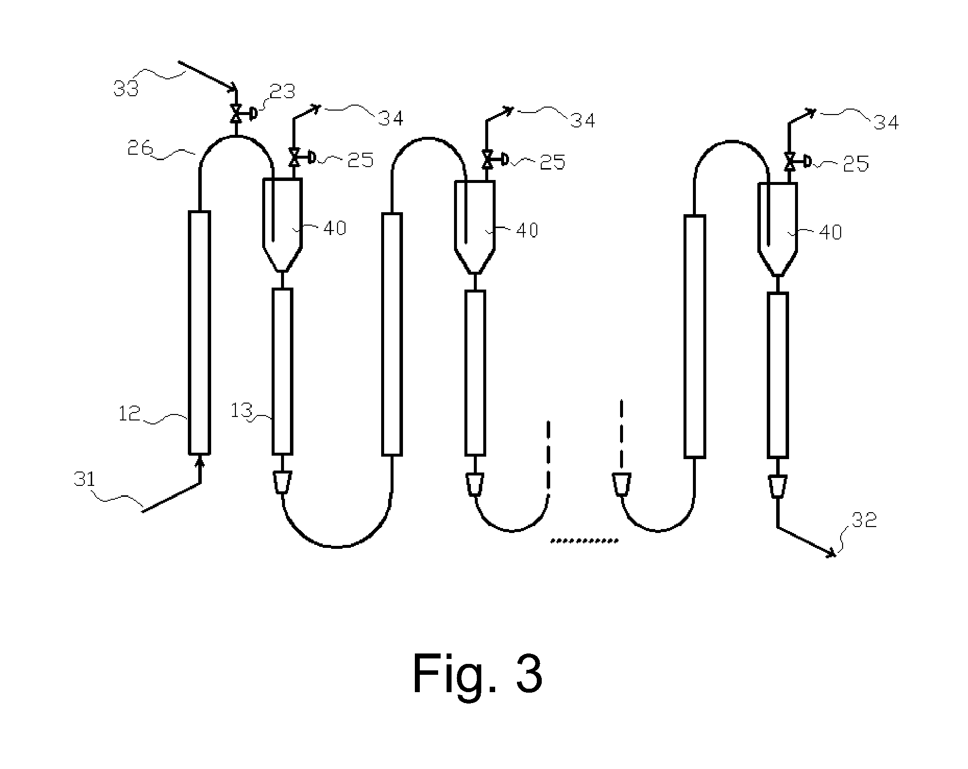
[0076]FIGS. 4 and 5 illustrate an example of a phase separator to be used with the embodiment “M3” described above.

[0077]The flow coming from the connection (26, FIG. 3) is fed to the telescope (66) by means of the flange (61) which introduces the fluid into the separator (65).

[0078]The phase separator (65) consists of a section of pipe having a diameter (D2) much greater than the diameter (D1) of the inlet pipe (66). The ratio between D2 and D1 is generally at least 1.2. The ratio between D2 and D1 preferably ranges from 1.5 to 10; even more preferably, the ratio between D2 and D1 ranges from 2 to 5.

[0079]The height of the outflow (H2) is typically lower than the height of the cylindrical section of the separator (H1), so as to maximize the separation of the gaseous phase. The fluid thus degassed passes to the descending duct (13, FIG. 3) through the flange (62).

[0080]The angles (A1) and (A2) for the connection of the degasser to the telescope (66) and descending duct (62) can have...

example a2

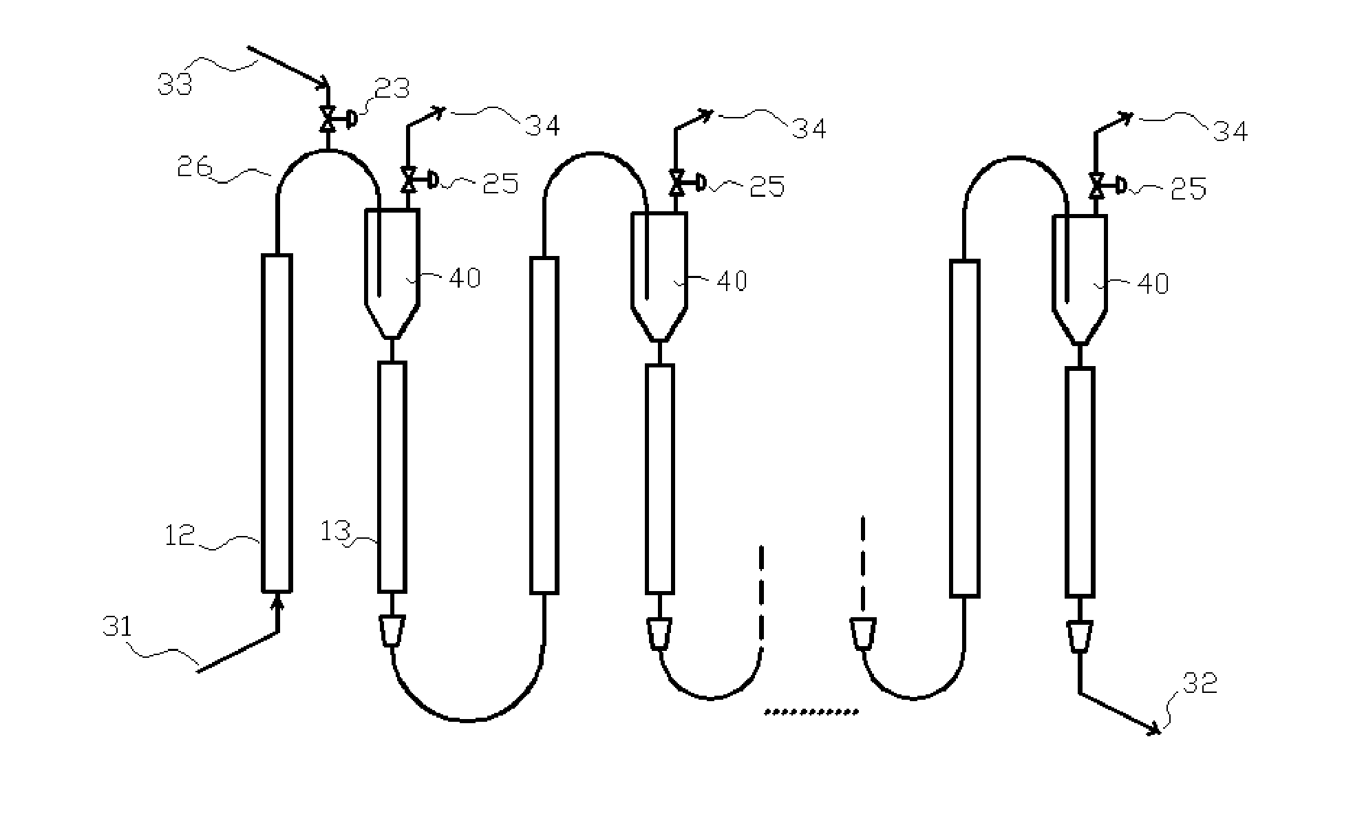
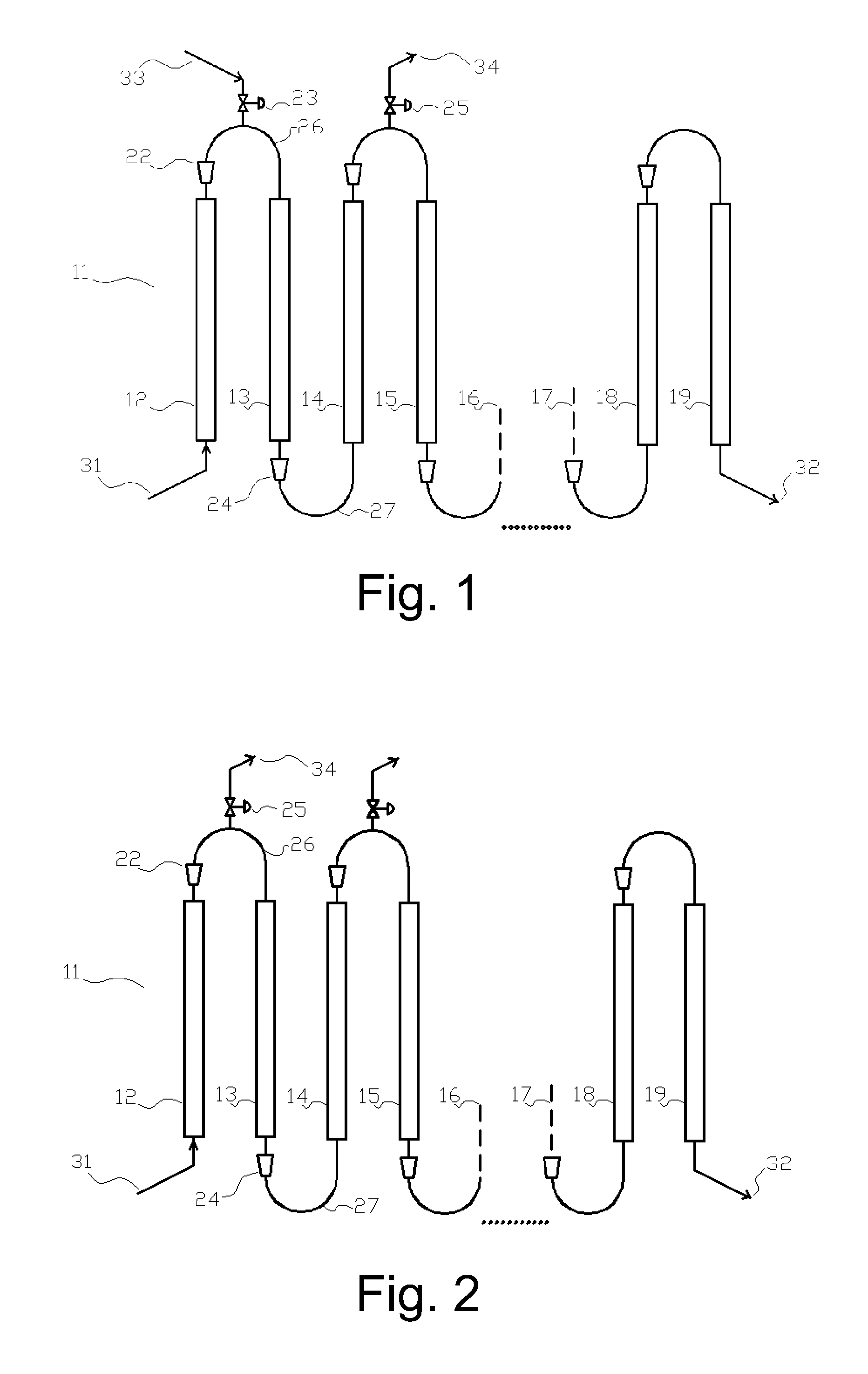
[0084]With reference to the embodiments described above, a stream richer in gaseous phase (34) can be withdrawn from the upper area of the ascending ducts (12; 14; 16; and descending ducts (13; 15; 17; or from the connection section (26). Alternatively, said stream can be withdrawn from the separation device (40) connected between the two ducts, as illustrated in the embodiment “M3” described above.

[0085]A filtering can be useful for preventing the non-gaseous components of said stream richer in gaseous phase from generating blockages or malfunctioning of the equipment downstream of said stream, such as for example the valves (25) which can be installed for the regulation and control of the outgoing flow.

[0086]The filtering element can be advantageously situated inside or on the wall of the separation device or elements mentioned above. Alternatively, it can be applied along the outgoing duct of the flow rich in gaseous phase. In the latter case, said filtering element is preferably...

example 1

[0095]A device is constructed for the depressurization of a fluid according to the embodiment “M2” described above.

[0096]The fluid (31) at the inlet of the depressurizer consists of a mixture of water, fed at a flow-rate of 7 tons per hour, and air, fed at a flow-rate of 1,500 normal litres per hour.

[0097]The first pair of ducts is described as follows. The ascending duct (12) consists of a steel pipe, having a nominal diameter of 3 inches (internal diameter, as per schedule, 77.83 mm), a length of 3,000 mm, vertically positioned. The section change (22) consists of a commercial reduction from 3 inches (7.62 cm) to 4 inches (10.16 cm) (nominal values). The curved section (26) consists of two commercial curves at 90° interspaced by a straight horizontal section of 200 mm, both of 4 inches (10.16 cm), on which a mouth connected to a ball valve (25), is inserted. The other end of the ball valve is open towards the atmosphere. The descending section (13) has a nominal diameter of 4 inch...


PUM

PropertyMeasurementUnit
temperatureaaaaaaaaaa
heightaaaaaaaaaa
relative pressureaaaaaaaaaa

Abstract

The device of the present invention allows the pressure of a certain fluid to be reduced without reductions in the cross sectional area or organs in movement. The pressure reduction is obtained by passing the fluid to be depressurized, in sequence, through a plurality of pairs of steps. In the first step of each pair, part of the pressure energy of the fluid is converted to gravitational potential; in the second step the gravitational potential is converted into thermal energy, so as to prevent the reconversion of the same into pressure energy.

Description

FIELD OF THE INVENTION[0001]The present invention relates to a process for the depressurization of fluids and the device suitable for the purpose.[0002]More specifically, the present invention relates to a process for the depressurization of fluids (liquids, or liquid mixtures containing a gaseous phase) which can carry solid particles or agglomerates. The present invention also relates to the device and relative uses.[0003]The device of the process, object of the present invention, can be advantageously used for reducing the pressure of fluids which contain solid parts or which contain material which could be modified if subjected to friction or excessive shear stress; or for reducing the pressure of dangerous fluids or fluids which operate in high-reliability processes, where maintenance interventions and the probability of breakdowns must be reduced to the minimum; or again for reducing the pressure of fluids which, for process or product reasons, advance at a low rate.[0004]In p...

Claims


Application Information

Patent Timeline
Patent Type & Authority Applications(United States)
IPC IPC(8): B01D19/00
CPCB01D19/0042B01D19/0057B01D19/00
Inventor FELISARI, RICCARDOCASALINI, ALESSANDRO
Owner VERSALIS SPA
Features
  • R&D
  • Intellectual Property
  • Life Sciences
  • Materials
  • Tech Scout
  • Unparalleled Data Quality
  • Higher Quality Content
  • 60% Fewer Hallucinations
Learn More