Eureka AIR delivers breakthrough ideas for toughest innovation challenges, trusted by R&D personnel around the world.

Sequential latch for palletized cargo

Active Publication Date: 2013-12-19
THE BF GOODRICH CO
View PDF1 Cites 11 Cited by
  • Summary
  • Abstract
  • Description
  • Claims
  • Application Information

AI Technical Summary

Benefits of technology

The present invention is a cargo handling system that can be locked and unlocked sequentially. The system includes load restraining rail assemblies that capture the sides of the pallet and a shaft assembly with lock pawls that engage with the pallet. The system can lock and unlock multiple pallets by rotating the shaft assembly and has the advantage of being efficient and easy to use.

Problems solved by technology

The limited space available between the loaded pallets and the cabin wall makes it difficult to ascertain the locked or unlocked status of the individual cargo locks and also dictates that the locking and unlocking action be done from a remote location, where a human operator can fit.
The cargo handling system of Naffa, however, is extraordinarily complex, consisting of multiple interconnected lock mechanisms, each of which includes dozens of moving springs, actuator rods, pivots, linkages, gear sectors, and other moving parts.

Method used


Image

  • Sequential latch for palletized cargo
  • Sequential latch for palletized cargo
  • Sequential latch for palletized cargo

Examples


Embodiment Construction

[0016]The drawing figures are intended to illustrate the general manner of construction and are not necessarily to scale. In the detailed description and in the drawing figures, specific illustrative examples are shown and herein described in detail. It should be understood, however, that the drawing figures and detailed description are not intended to limit the invention to the particular form disclosed, but are merely illustrative and intended to teach one of ordinary skill how to make and / or use the invention claimed herein and for setting forth the best mode for carrying out the invention.

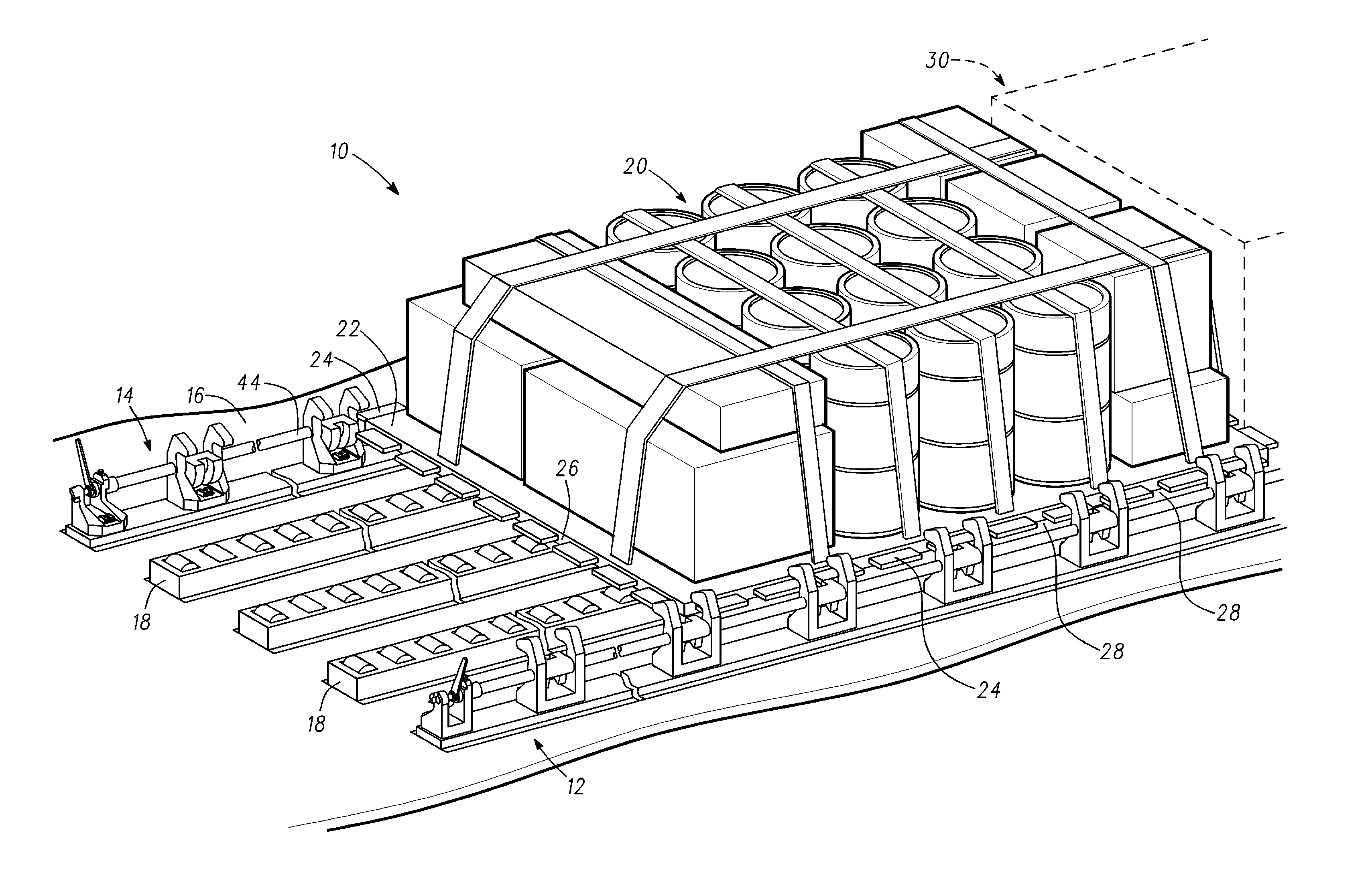
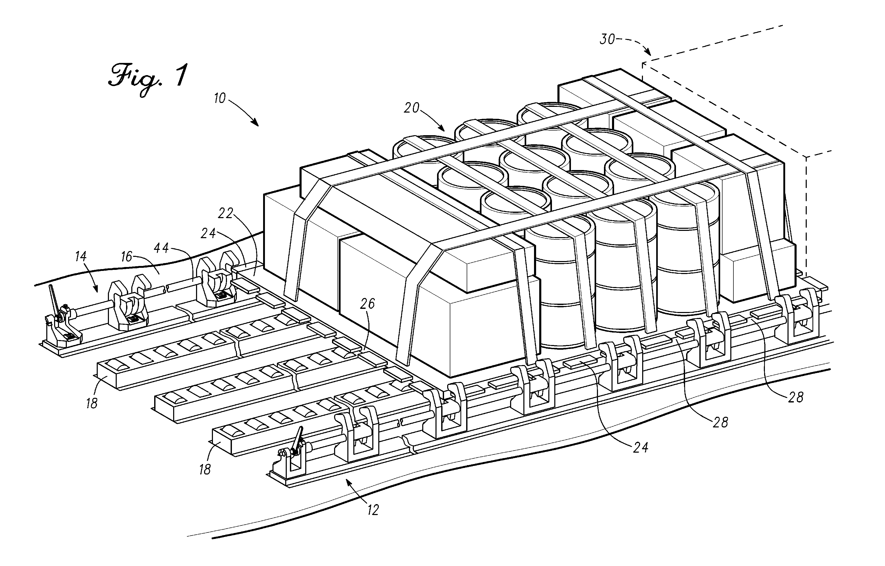
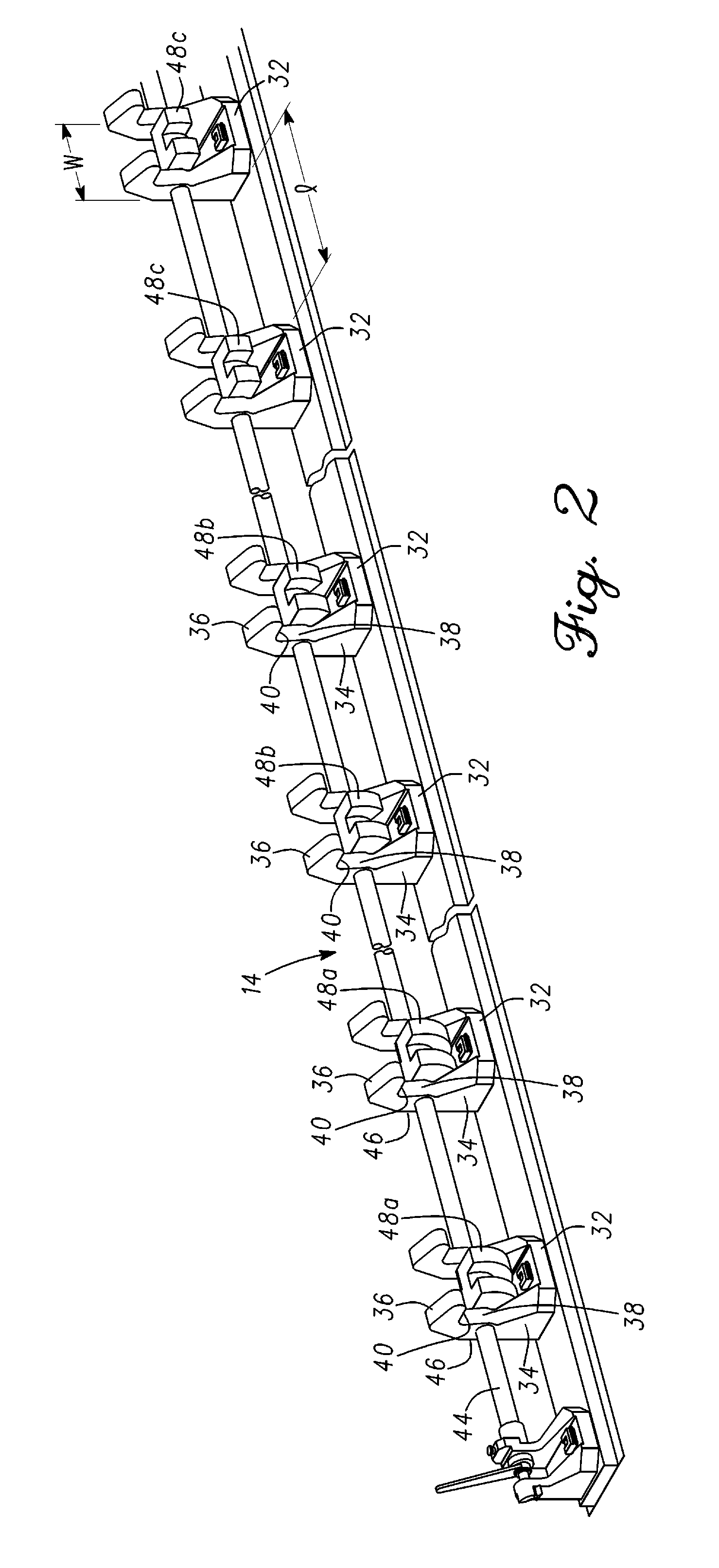
[0017]With reference to FIGS. 1 and 2 as a cargo handling apparatus 10 incorporating features of the present invention comprises a port load restraining rail assembly 12 and a starboard load restraining rail assembly 14 each of which is attached to the aircraft floor 16. Cargo handling apparatus 10 further comprises a plurality of roller conveyors 18 which are adapted to permit a load 20 secure...


PUM


Abstract

An aircraft cargo handling system has a pair of load restraining rail assemblies, each of which has a shaft assembly running substantially parallel to the longitudinal axis of the aircraft. The shaft assembly has a plurality of lock pawls, each of which comprises a body having a cylindrical pallet-engaging surface. The pallet engaging surfaces of the lock pawls have increasing included angles at stations moving toward the front of the aircraft (or vice versa). This enables the pallets to be locked in place sequentially by rotating the shaft assembly an predetermined angular rotation each time a pallet is loaded. Unloading of the aircraft is carried out in the reverse order, by rotating the shaft assembly in the opposite direction in steps to unlock each pallet individually as the aircraft is unloaded.

Description

BACKGROUND OF THE INVENTION[0001]This invention relates generally to aircraft interior equipment and, in particular, to aircraft cargo handling systems.[0002]In 1957, the United States Air Force adopted a standardized system to facilitate cargo handling aboard military airlift aircraft. The Air Force cargo handling system is known as “Materials Handling Support System 463L” or simply “463L System.” A central component of the 463L system is the HCU-6 / E pallet, sometimes referred to simply as the “463L pallet,” which is a standardized pallet, 108 inches wide by 88 inches long by 2-¾ inches thick, typically made of aluminum plates top and bottom with a balsa wood core, framed on all sides by aluminum rails. The rails have 22 steel tie-down rings attached so that there are six rings on each long side and five rings on each short side. The rails also have notches approximately 1-¼ inches deep by 2-¾ inches wide evenly spaced approximately every 10 inches along all sides.[0003]The aircraf...

Claims


Application Information

Patent Timeline
IPC IPC(8): B64D9/00
CPCB64D9/003B60P7/08B60P7/13
Inventor LARSON, WALLACE H.BROWN, JAMES R.
Owner THE BF GOODRICH CO
Why Eureka
Eureka Blog
Learn More