
Digital Electrical Routing Control System for Use with Electrical Storage Systems and Conventional and Alternative Energy Sources

a control system and digital technology, applied in the integration of power network operation systems, dc source parallel operation, emergency power supply arrangements, etc., can solve the problems of grid-tie inverter tripping, not easy to be accommodated by conventional grid-based power systems that currently exist, and not provide a reliable energy service on its own

Inactive Publication Date: 2013-12-19
AGMONITOR INC
View PDF6 Cites 38 Cited by
  • Summary
  • Abstract
  • Description
  • Claims
  • Application Information

AI Technical Summary

Benefits of technology

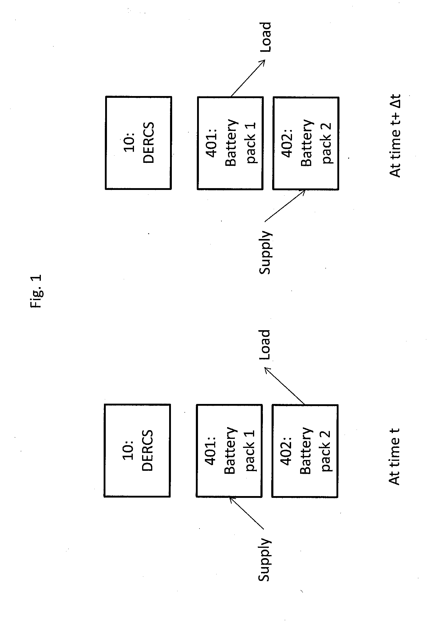
This patent describes a controller that can charge two batteries simultaneously. This means that while one battery is being used to power a load, the other battery can be charged as well. This technology allows for more efficient use of batteries, reducing the need for multiple batteries and ensuring a consistent power supply.

Problems solved by technology

It does not provide a reliable energy service on its own compared to conventional grid-based power systems.
Moreover, it isn't easily accommodated by the conventional grid-based power systems that currently exist.
In a time of blackout, however, grid-tie inverters become tripped into an off position, as they no longer receive the oscillating signal from the AC power of the grid that indicates presence of AC power.
When tripped off, however, the alternative energy sources to which they are attached also become disconnected from the customer who desires to use the power generated thereby.

Method used


Image

  • Digital Electrical Routing Control System for Use with Electrical Storage Systems and Conventional and Alternative Energy Sources
  • Digital Electrical Routing Control System for Use with Electrical Storage Systems and Conventional and Alternative Energy Sources
  • Digital Electrical Routing Control System for Use with Electrical Storage Systems and Conventional and Alternative Energy Sources

Examples


Embodiment Construction

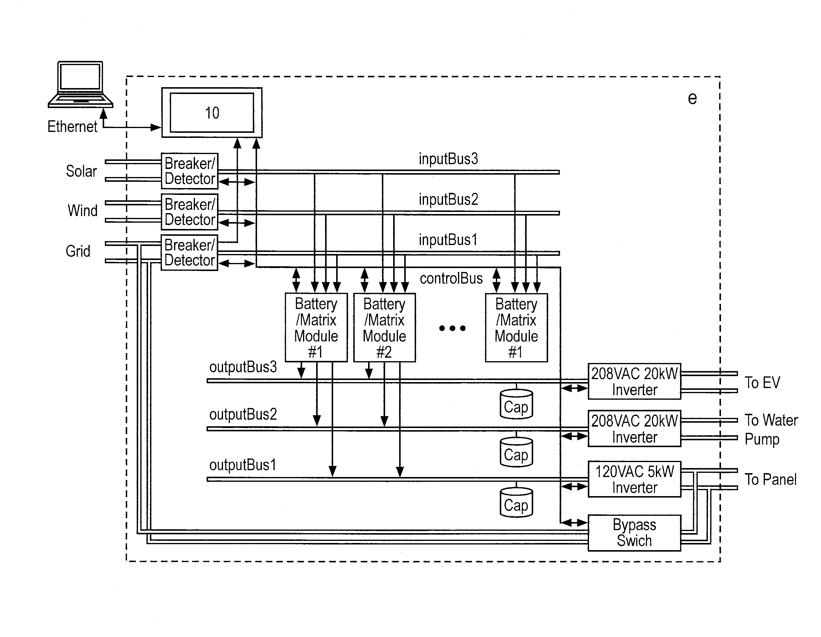
[0077]Described herein is a digital electrical routing control system for use with electrical storage systems and conventional and alternative energy sources.

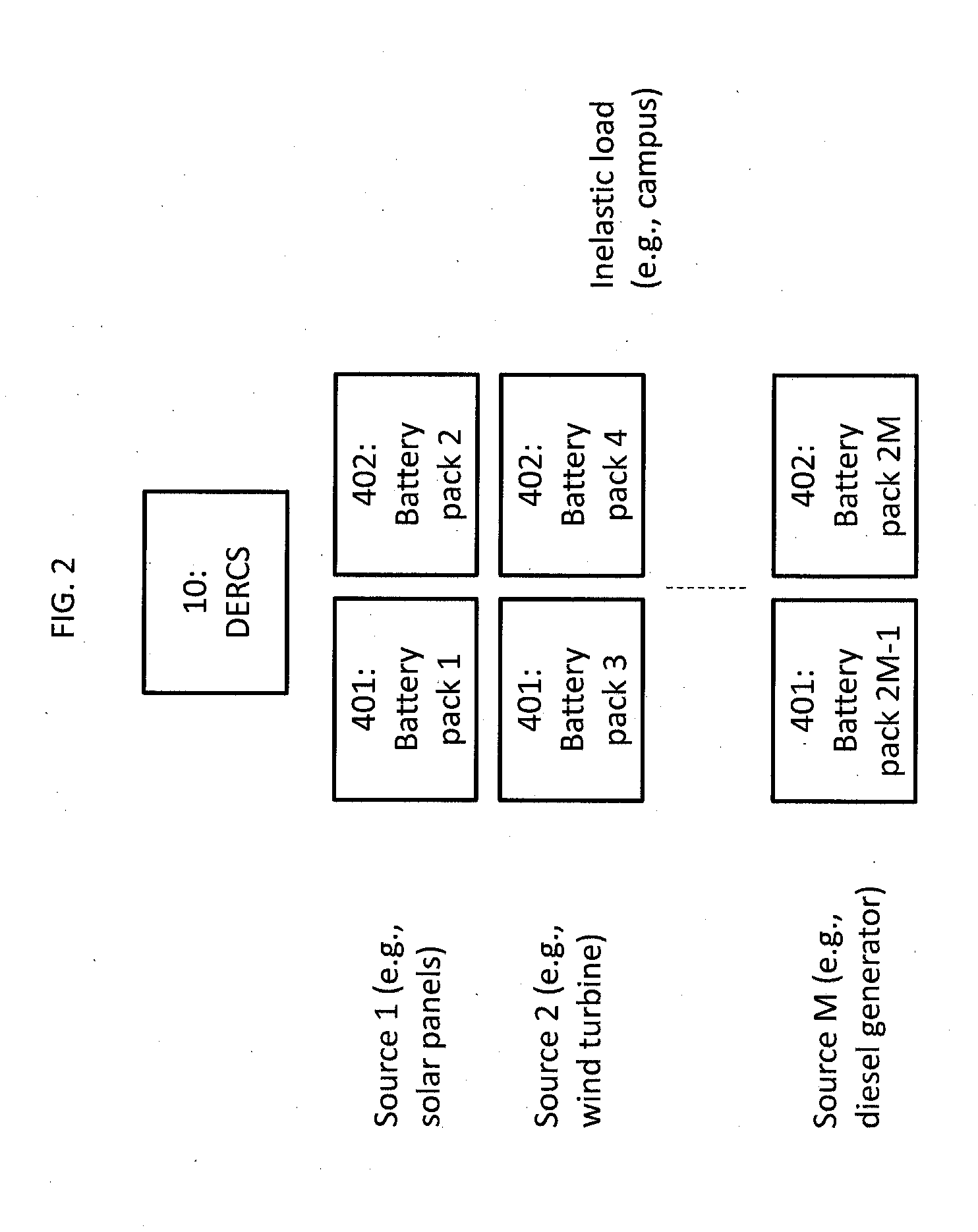
[0078]In a preferred embodiment, an array of two or more batteries are used to de-couple the load(s) and energy source(s), and the digital electrical routing control system provides the functionality to ensure correct energy flow between various energy sources and loads, through the batteries that also store electrical power obtained from the various energy sources. The digital electrical routing control system described herein does not require a meter or an analog feedback-loop, as will be seen from the descriptions hereafter.

[0079]From a functional perspective, the digital electrical routing control system described herein allows for the connections among batteries, load(s), and source(s) to be updated at regular and slow intervals, 15 minutes or more, for instance. This period of time can be used to fine up solar energy to p...


PUM


Abstract

Described is a digital electrical routing control system for use with electrical storage systems and conventional and alternative energy sources, and methods of using the same. In one aspect is described a method of determining an amount of energy used by a load using a computer, with the energy being provided from a first battery and a second battery, and with other energy being supplied to charge the first battery and the second battery, the method comprising the steps of: initiating, using the computer, charging of the first battery with the other energy while the second battery is being drained by connection to the load; initiating, using the computer, charging of the second battery with the other energy while the first battery is being drained by connection to the load; and detecting, using the computer, an amount of energy consumed during an interval of time based upon an amount of charging of the first battery and the second battery during the interval of time.

Description

RELATED APPLICATIONS[0001]This application claims priority to U.S. Provisional Application Nos. 61 / 646,015 filed May 11, 2012, 61 / 650,484 filed May 23, 2012, and 61 / 694,907 filed Aug. 30, 2012, which applications are expressly incorporated by reference herein and is related to U.S. patent application Ser. No. 13 / 844,648 entitled PEER-TO-PEER TRANSACTION AND MOBILE ENERGY SERVICE being filed concurrently with this application on Mar. 15, 2013, which application is expressly incorporated by reference herein.FIELD OF THE RELATED ART[0002]Described is a digital electrical routing control system for use with electrical storage systems and conventional and alternative energy sources.BACKGROUND OF THE RELATED ART[0003]Conventional grid-based electrical power distribution is well established. Grid-based power relies on large-scale generators and power meters at the end of the distribution network in order to measure the electricity used by a customer and be able to charge for it.[0004]Power...

Claims


Application Information

Patent Timeline
IPC IPC(8): H02J4/00G01R31/36
CPCH02J4/00G01R31/36G01R22/10H02J3/008H02J3/32H02J7/0019H02J7/0068H02J7/35Y02B70/3225Y04S20/222Y04S20/242G06F1/26H02J2310/64H02J2310/14H02J2300/40H02J2300/28H02J2310/48H02J3/322H02J2300/24H02J3/381H02J7/0025H02J3/14H02J7/0063Y02B70/30Y02E10/56Y02E10/76Y02T90/167Y04S30/12Y04S30/14Y02E70/30Y04S50/10
Inventor JERPHAGNON, OLIVIER L.
Owner AGMONITOR INC
Learn More