Arrangement for the inductive wireless delivery of energy

a technology of inductive wireless and energy delivery, applied in the direction of transformer/inductance circuit, circuit arrangement, inductance, etc., can solve the disadvantages of mixing both variants, high magnetic flux density, and inability to heat the metallic body. , to achieve the effect of minimizing the installation spa

Active Publication Date: 2013-12-19
SIEMENS AG
View PDF8 Cites 6 Cited by
  • Summary
  • Abstract
  • Description
  • Claims
  • Application Information

AI Technical Summary

Benefits of technology

[0008]The invention has recognized that the magnetically active surfaces can be increased, thereby lowering the flux density, by distributing a floor-mounted circular winding onto two circular windings with different current directions. This results in two magnetic field strength lobes having different directions via which a smaller solenoid winding design—in particular a vehicle-mounted winding—can now also be advantageously operated. A possible heating of metallic foreign bodies that exceeds permissible limits is thereby simultaneously avoided.
[0010]According to another advantageous feature of the present invention, the first and second coils can be arranged in one plane. In this way, the required installation space is minimized and the design is flat, which accommodates the installation as a floor-mounted charging station for driving electrically operated vehicles for instance. The coils can then be advantageously arranged next to each other.
[0011]According to another advantageous feature of the present invention, the first and second coils can be configured of equal size. Since the electrical actuation of the coils must take account of their dimensions and geometry, the similar design of both coils ensures that the controller does not have to be made unnecessarily complex.

Problems solved by technology

A mixture of both variants is disadvantageous owing to the sub-optimal coupling.
The solenoid design is smaller with the same coupling, but causes higher magnetic flux densities, which can lead to impermissible heating of the metallic body in the region of the magnetic field.
The circular design has a lower flux density, owing to its larger surface area, but it is less readily able to be mounted on the vehicle.

Method used


Image

  • Arrangement for the inductive wireless delivery of energy
  • Arrangement for the inductive wireless delivery of energy

Examples


Embodiment Construction

[0018]Throughout all the figures, same or corresponding elements may generally be indicated by same reference numerals. These depicted embodiments are to be understood as illustrative of the invention and not as limiting in any way. It should also be understood that the figures are not necessarily to scale and that the embodiments are sometimes illustrated by graphic symbols, phantom lines, diagrammatic representations and fragmentary views. In certain instances, details which are not necessary for an understanding of the present invention or which render other details difficult to perceive may have been omitted.

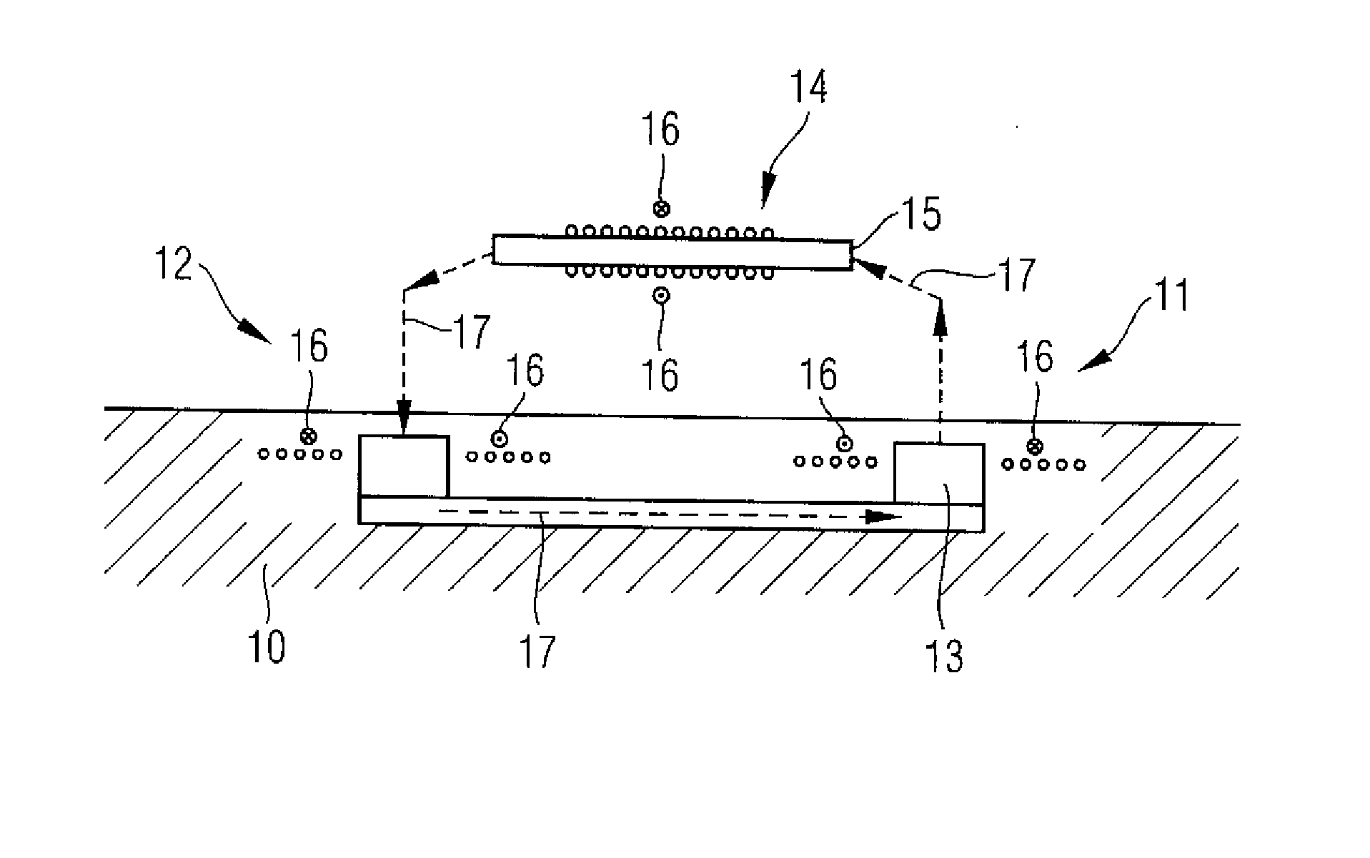
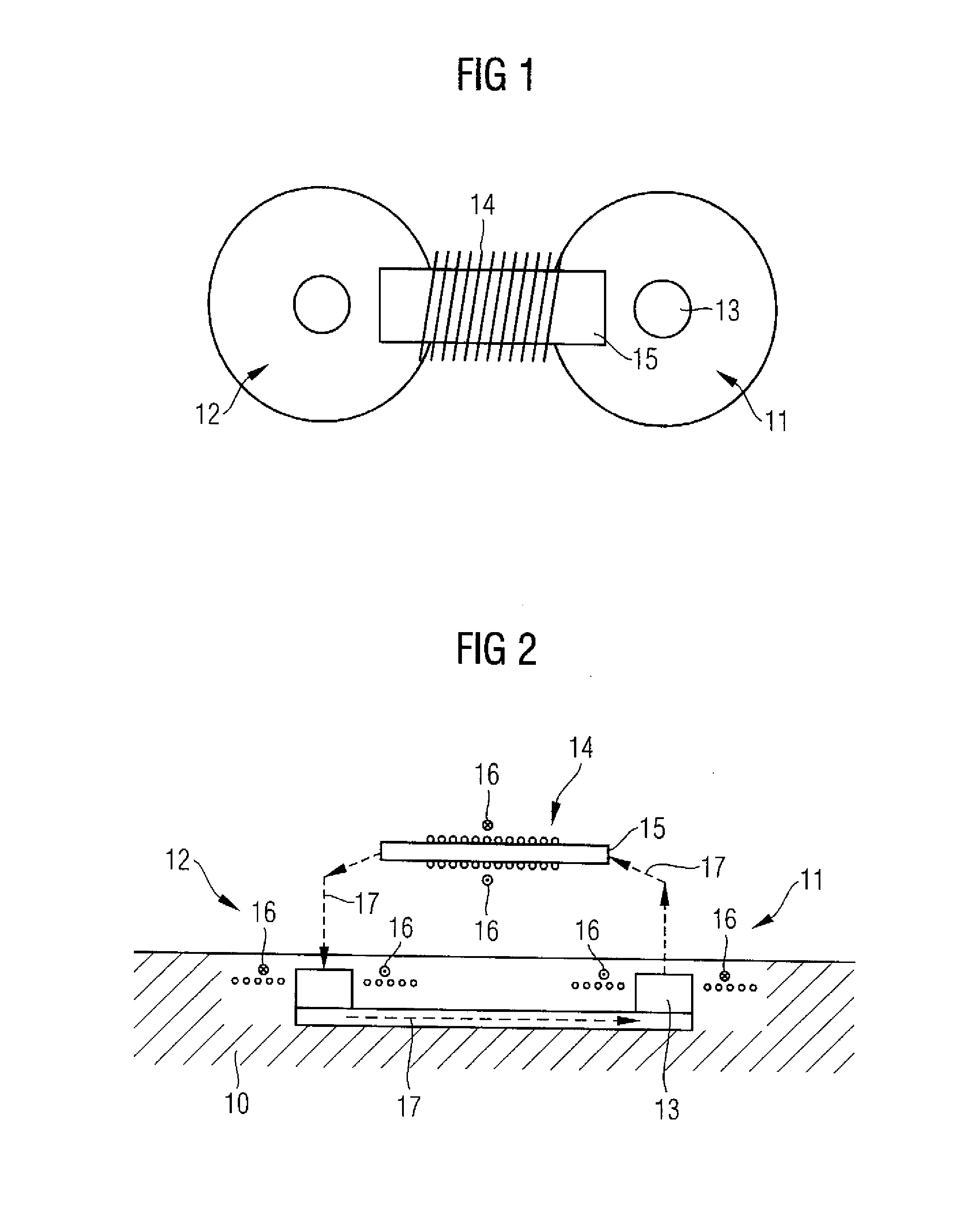
[0019]Turning now to the drawing, and in particular to FIG. 1, there is shown a schematic top view of a floor-mounted coil arrangement for electric vehicles together with a vehicle-mounted solenoid coil, which is used to receive the supplied energy. The vehicle-mounted coil is fixed to a vehicle (not shown in more detail), while the floor-mounted charging station is embedded...


PUM

PropertyMeasurementUnit
energyaaaaaaaaaa
electrically conductiveaaaaaaaaaa
sizeaaaaaaaaaa

Abstract

An arrangement for the inductive wireless transmission of energy to a receiver coil of an electrically operated vehicle includes a controllable power supply, an electrically conductive first coil of circular shape, and an electrically conductive second coil of circular shape. The first and second coils are connected to the controllable power supply such that a current direction in the second coil is directed opposite to a current direction in the first coil.

Description

CROSS-REFERENCES TO RELATED APPLICATIONS[0001]This application claims the priority of German Patent Application, Serial No. 10 2012 209 898.4, filed Jun. 13, 2012, pursuant to 35 U.S.C. 119(a)-(d), the content of which is incorporated herein by reference in its entirety as if fully set forth herein.BACKGROUND OF THE INVENTION[0002]The present invention relates to an arrangement for the inductive wireless delivery of energy.[0003]The following discussion of related art is provided to assist the reader in understanding the advantages of the invention, and is not to be construed as an admission that this related art is prior art to this invention.[0004]Windings of either a circular or solenoid design are used in the wireless charging of electric vehicles. Circular design refers to a coil in which the wires extend spirally in one plane, solenoid design refers to a winding in the manner of a coil. A mixture of both variants is disadvantageous owing to the sub-optimal coupling. The soleno...

Claims


Application Information

Patent Timeline
Patent Type & Authority Applications(United States)
IPC IPC(8): H01F38/14
CPCH01F38/14H02J50/10
Inventor KOMMA, THOMAS
Owner SIEMENS AG
Why Eureka
Try Eureka