Bi-telecentric interferometer continuous zoom imaging device

a technology of interferometer and imaging device, which is applied in the direction of measurement device, instruments, optics, etc., can solve the problems of difficulty in maintenance, possible optical route deviation, design and assembly of opto-mechanical equipment that is rather complicated, etc., to reduce the possibility of optical route deviation, facilitate assembly and maintenance, and raise the overall stiffness

Inactive Publication Date: 2013-12-19
HSINTEK OPTICAL INSTR CORP
View PDF6 Cites 1 Cited by
  • Summary
  • Abstract
  • Description
  • Claims
  • Application Information

AI Technical Summary

Benefits of technology

[0008]In view of the problems and drawbacks of the prior art, a major objective of the present invention is to provide a bi-telecentric interferometer continuous zoom imaging device, so that various optical modules can be assembled integrally into a machine body, so as to raise its overall stiffness, facilitate assembly and maintenance, and reduce the possibility of optical route deviation.

Problems solved by technology

Presently, the design and assembly of the opto-mechanical equipment is rather complicated, and the calibrated optical route is easy to be affected by external forces to induce optical axis deviations, hereby causing difficulty in maintenance.
However, during transportation, the main body structure is apt to have the problem of insufficient stiffness due to its design structure, thus leading to the possibility of optical route deviation.
Moreover, upon being impacted from outside, the main body structure will generate vibrations, hereby producing optical route deviations.
Furthermore, since the optical elements are not modularized, and are placed separately in the main body structure, such that when some of the elements break down, the entire structure must be detached, checked, repaired, or replaced, and that is tedious, costly, time consuming, and of low efficiency.
In addition, the CCD of the optical-mechanical device and the attached lens are heavy and voluminous.
In adjusting focus, CCD has to be adjusted, to cooperate with the imaging plane, and that will cause the vibration and deviations of gravitational center of the entire main-body structure, hereby making the process of adjusting the CCD and lens very complicated.
In addition to the shortcomings of the conventional opto-mechanical device mentioned above, the quality of the interference fringes depends on the imaging system, so that when the distance to the object-to-be-measured is changed, the magnification ratio, distortion, and resolution of the imaging system are changed, thus affecting its accuracy of measurement.
Therefore, presently, the design and performance of continuous zoom imaging device are not quite satisfactory, and it has much room for improvements.

Method used


Image

  • Bi-telecentric interferometer continuous zoom imaging device
  • Bi-telecentric interferometer continuous zoom imaging device
  • Bi-telecentric interferometer continuous zoom imaging device

Examples


Embodiment Construction

[0021]The purpose, construction, features, functions and advantages of the present invention can be appreciated and understood more thoroughly through the following detailed description with reference to the attached drawings.

[0022]The structure of conventional optical-mechanical device is rather complicated, and optical route deviations are liable to occur due to impact from outside or vibration during transportation, such that its transportability is insufficient and it assembly, detachment, and maintenance are complicated and inconvenient. In order to improve the shortcomings of the prior art, the present invention provides a bi-telecentric interferometer continuous zoom imaging device, to raise its overall performance and stability in application.

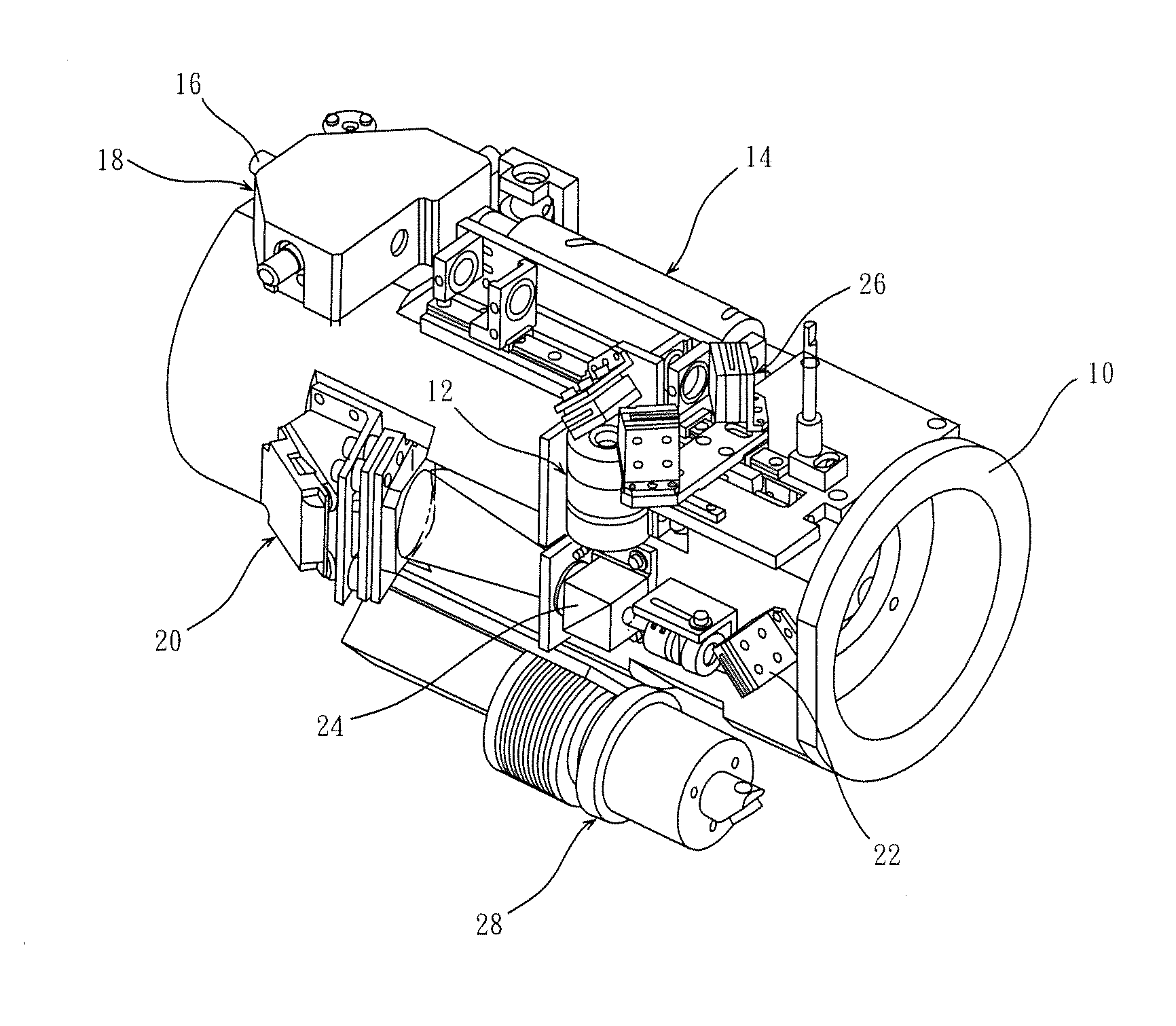
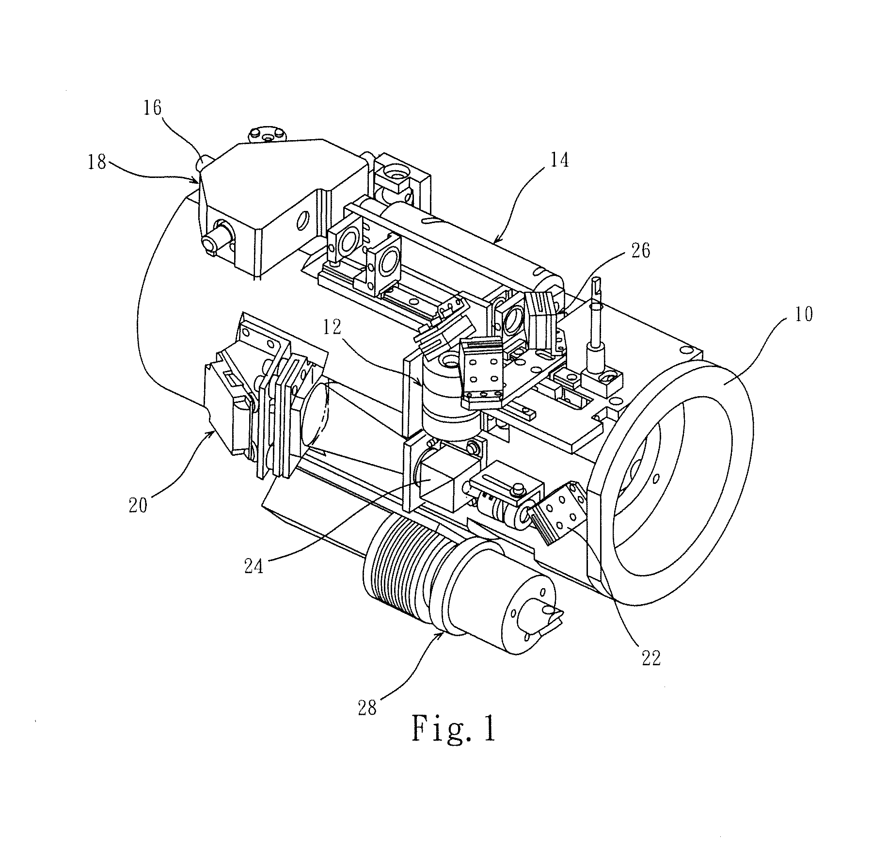
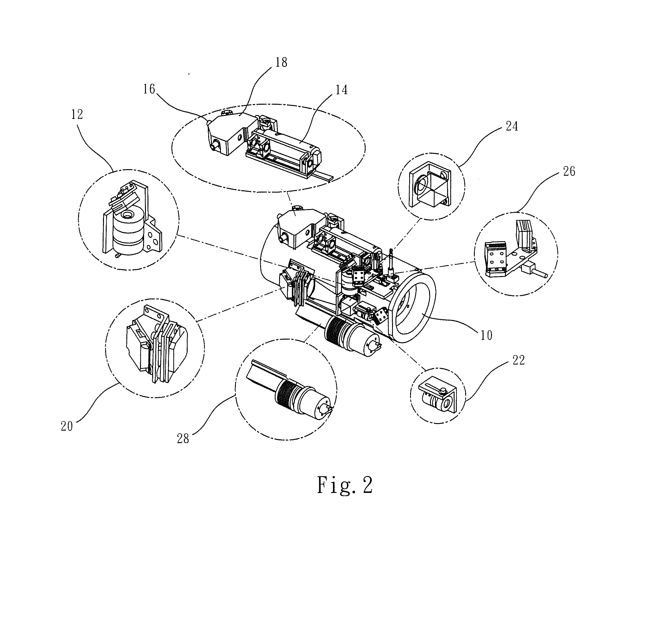
[0023]Firstly, the improvement of structure design is described in detail. Refer to FIGS. 1 and 2 for a perspective view of a bi-telecentric interferometer continuous zoom imaging device according to the present invention, and an enlarg...


PUM


Abstract

A bi-telecentric interferometer continuous zoom imaging device, wherein a collimation object lens set, a telecentric imaging module, a telecentric continuous zoom module, and a CCD of modular design are formed on an integral circular tube main body, and can be calibrated and positioned separately. Then, a multi-partition isolation design is used to partition a housing into independent space for said various modules, to facilitate maintenance and also achieve customization. Collimation object lens set converts parallel light beams of interference pattern into a convergent light beam, and guides it to an imaging route through optical route adjusting means. Then, telecentric imaging module converts interference pattern on imaging route into an telecentric image parallel to optical axis, and telecentric continuous zoom module adjusts a magnifying ratio of telecentric image, then outputs an object image to form it on CCD, thus improving optical distortion and inferior resolution of the prior art.

Description

BACKGROUND OF THE INVENTION [0001]1. Field of the Invention[0002]The present invention relates to a bi-telecentric interferometer continuous zoom imaging device, and in particular to a bi-telecentric interferometer continuous zoom imaging device, that is modular in design and capable of facilitating assembly, repair, maintenance, and customization, to minimize optical distortion through bi telecentric imaging, hereby raising the measuring precision for object at large distance.[0003]2. The Prior Arts[0004]Along with the progress and development of precision measurement technology, the precise measurement of minute elements can be realized through optical means. Due to its advantages of high accuracy and non-destruction, it has been used widely in various sectors of the Industries. In this respect, an interferometer that is an opto-mechanical equipment capable of measuring optical elements or other physical quantities by means of optical interference is taken as example for explanati...

Claims


Application Information

Patent Timeline
Patent Type & Authority Applications(United States)
IPC IPC(8): G02B13/22
CPCG02B13/22G01B21/00G02B15/00
Inventor MENG, HSIEN-HUNGSHIUE, SHIN-GWOCHUNG, JIM
Owner HSINTEK OPTICAL INSTR CORP
Why Eureka
Try Eureka