Optical image lens system

a technology of optical image and lens system, applied in the field of compact optical image lens system, can solve the problems of unsolved optical design problems, unfavorable telephoto functionality, and the inability of conventional four-element lens structure to meet the requirements of compact optical lens system

Active Publication Date: 2013-12-19
LARGAN PRECISION
View PDF1 Cites 71 Cited by
  • Summary
  • Abstract
  • Description
  • Claims
  • Application Information

AI Technical Summary

Benefits of technology

[0008]According to one aspect of the present disclosure, an optical image lens system includes, in order from an object side to an image side, a first lens element, a second lens element, a third lens element, a fourth lens element, a fifth lens element and a sixth lens element. The first lens element with positive refractive power has a convex object-side surface. The second lens element has positive refractive power. The third lens element has positive refractive power. The fourth lens element has refractive power. The fifth lens element with positive refractive power is made of plastic material and has a convex object-side surface and a concave image-side surface, wherein at least one of the object-side surface and the image-side surface of the fifth lens element is aspheric. The sixth lens element with refractive power is made of plastic material and has a concave image-side surface, wherein the image-side surface of the sixth lens element changes from concave at a paraxial region to convex at a peripheral region, and at least one of an object-side surface and the image-side surface of the sixth lens element is aspheric. When a focal length of the optical image lens system is f, a focal length of the first lens element is f1, and a focal length of the second lens element is f2, the following relationship is satisfied: 0<|f / f1|+|f / f2|<1.3.

Problems solved by technology

However, the conventional four-element lens structure cannot satisfy these requirements of the compact optical lens system.
Although other conventional optical lens systems with five-element lens structure such as the ones disclosed in U.S. Pat. No. 8,000,030 and U.S. Pat. No. 8,000,031 enhance image quality and resolving power, these optical designs still reside with unsolved problems.
Since there are no three continuous lens elements closest to the object side with positive refractive power, it is not favorable for presenting its telephoto functionality in which the telephoto ratio is thereby limited.
These optical designs are also hard to keep the lens system compact while achieving for the same telephoto ratio.
Besides, these optical designs are not favorable for reducing the sensitivity of the lens system because its positive refractive power of these optical systems is not effectively distributed.

Method used


Image

  • Optical image lens system
  • Optical image lens system
  • Optical image lens system

Examples


1st embodiment

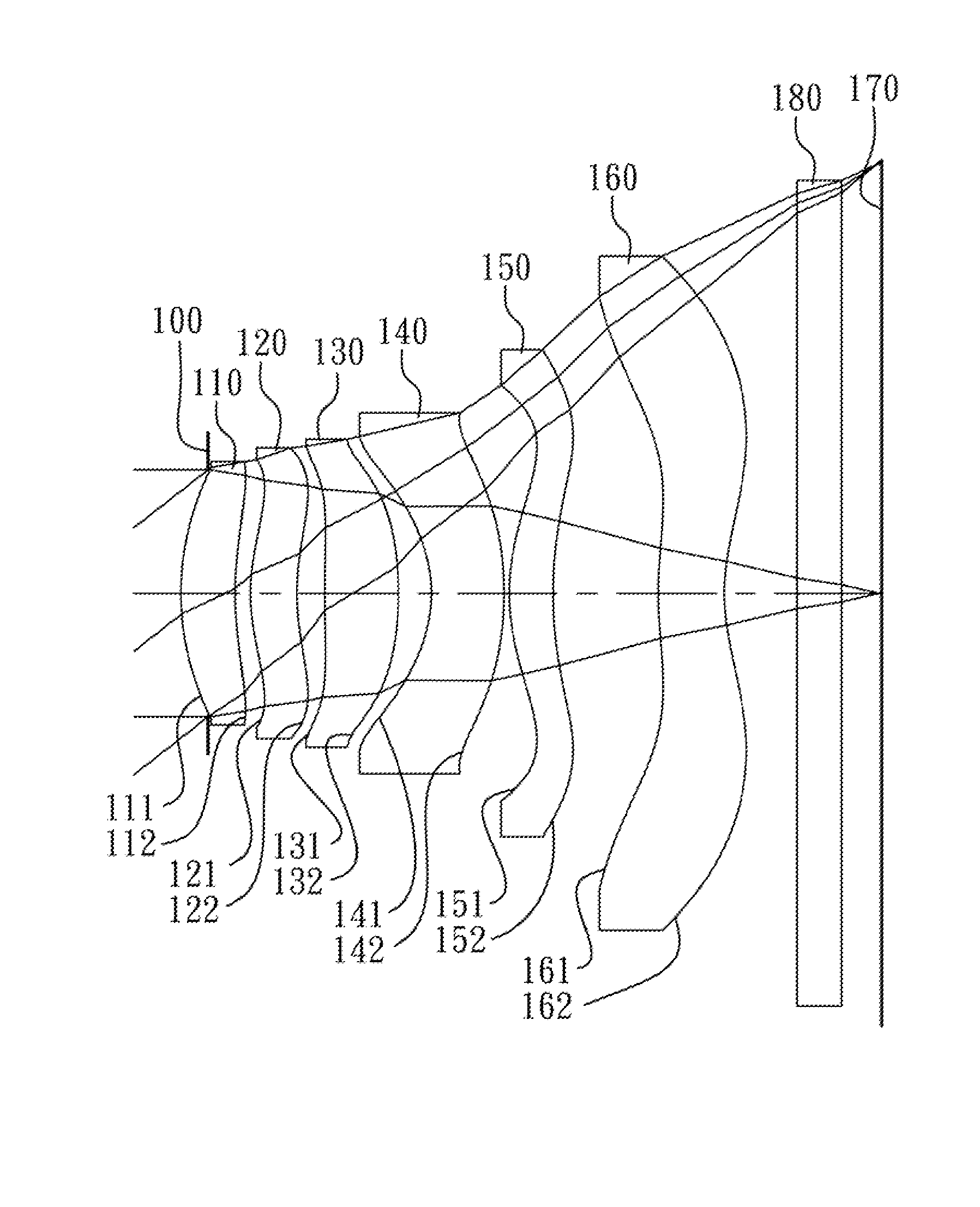
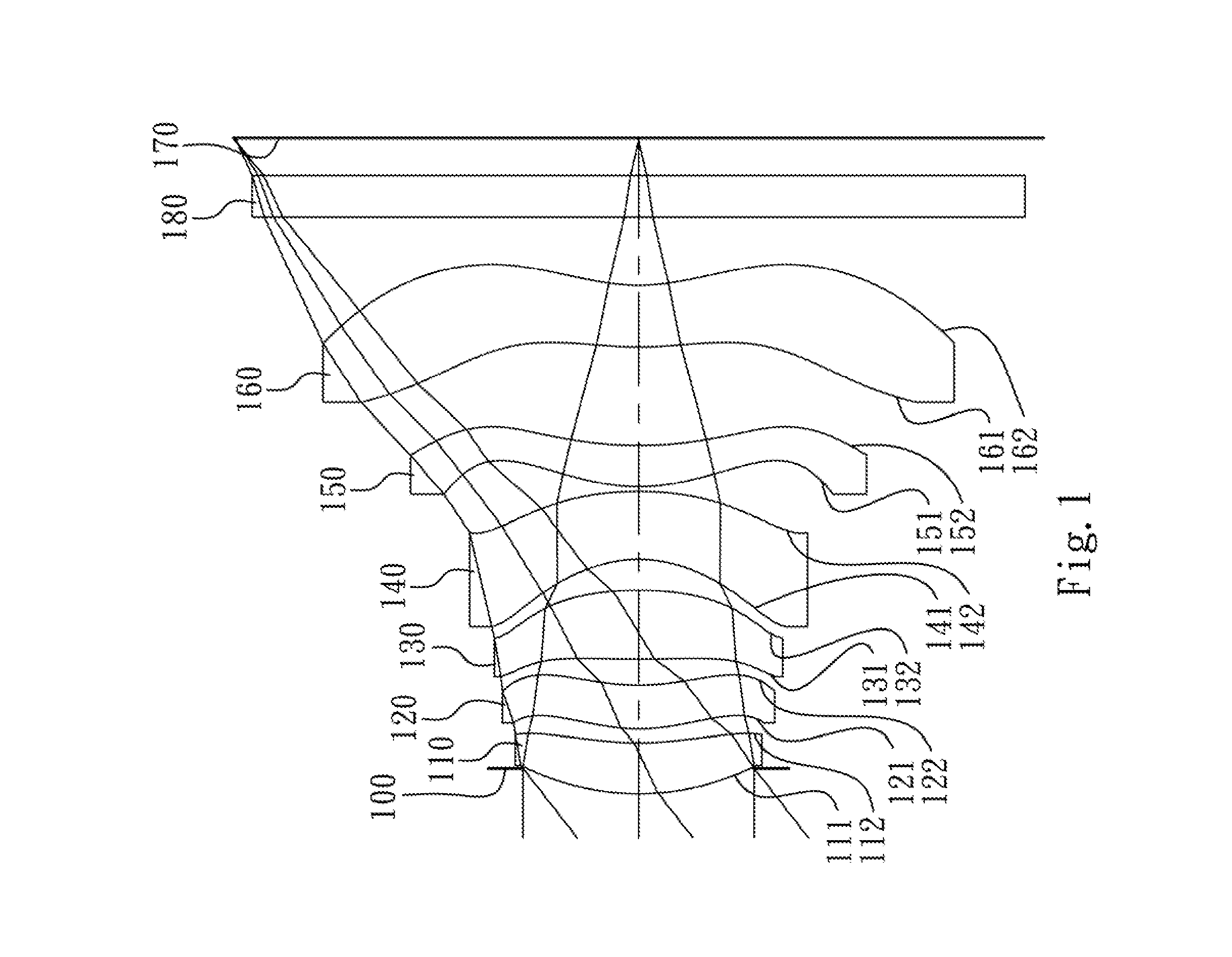
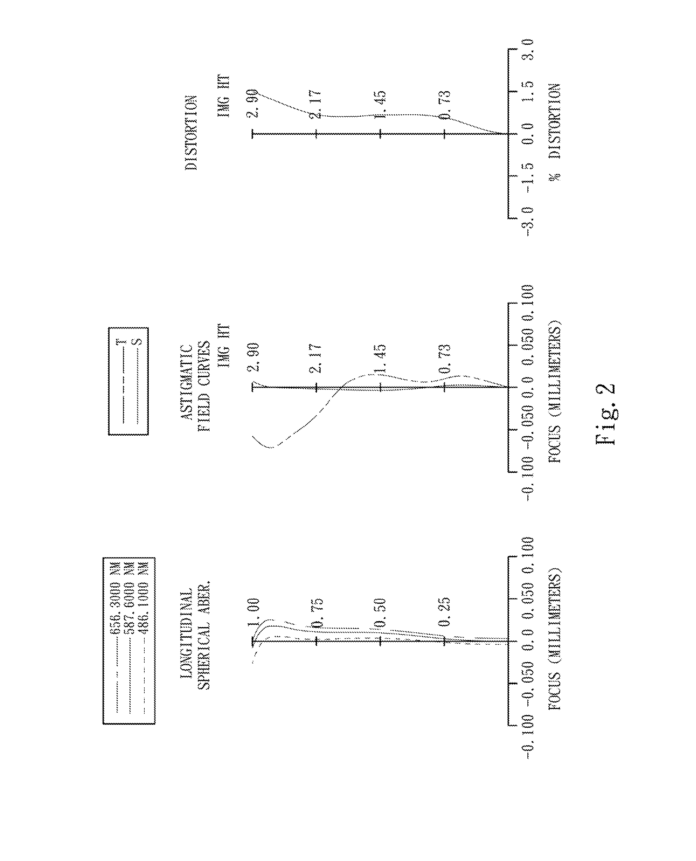
[0054]FIG. 1 is a schematic view of an optical image lens system according to the 1st embodiment of the present disclosure. FIG. 2 shows spherical aberration curves, astigmatic field curves and a distortion curve of the optical image lens system according to the 1st embodiment. In FIG. 1, the optical image lens system includes, in order from an object side to an image side, an aperture stop 100, a first lens element 110, a second lens element 120, a third lens element 130, a fourth lens element 140, a fifth lens element 150, a sixth lens element 160, an IR-cut filter 180, and an image plane 170.

[0055]The first lens element 110 with positive refractive power has a convex object-side surface 111 and a concave image-side surface 112. The first lens element 110 is made of plastic material and has the object-side surface 111 and the image-side surface 112 being aspheric.

[0056]The second lens element 120 with positive refractive power has a convex object-side surface 121, and an image-sid...

2nd embodiment

[0083]FIG. 3 is a schematic view of an optical image lens system according to the 2nd embodiment of the present disclosure. FIG. 4 shows spherical aberration curves, astigmatic field curves and a distortion curve of the optical image lens system according to the 2nd embodiment. In FIG. 3, the optical image lens system includes, in order from an object side to an image side, a first lens element 210, an aperture stop 200, a second lens element 220, a third lens element 230, a fourth lens element 240, a fifth lens element 250, a sixth lens element 260, an IR-cut filter 280, and an image plane 270.

[0084]The first lens element 210 with positive refractive power has a convex object-side surface 211 and a convex image-side surface 212. The first lens element 210 is made of plastic material and has the object-side surface 211 and the image-side surface 212 being aspheric.

[0085]The second lens element 220 with positive refractive power has a convex object-side surface 221, and an image-side...

3rd embodiment

[0093]FIG. 5 is a schematic view of an optical image lens system according to the 3rd embodiment of the present disclosure. FIG. 6 shows spherical aberration curves, astigmatic field curves and a distortion curve of the optical image lens system according to the 3rd embodiment. in FIG. 5, the optical image lens system includes, in order from an object side to an image side, a first lens element 310, an aperture stop 300, a second lens element 320, a third lens element 330, a fourth lens element 340, a fifth lens element 350, a sixth lens element 360, an IR-cut filter 380, and an image plane 370.

[0094]The first lens element 310 with positive refractive power has a convex object-side surface 311 and a concave image-side surface 312. The first lens element 310 is made of plastic material and has the object-side surface 311 and the image-side surface 312 being aspheric.

[0095]The second lens element 320 with positive refractive power has a convex object-side surface 321, and an image-sid...


PUM


Abstract

An optical image lens system includes, in order from an object side to an image side, a first lens element, a second lens element, a third lens element, a fourth lens element, a fifth lens element and a sixth lens element. The first lens element with positive refractive power has a convex object-side surface. The second lens element and the third lens element have positive refractive power. The fourth lens element has refractive power. The fifth lens element with positive refractive power is made of plastic and has a convex object-side surface and a concave image-side surface, wherein at least one surface thereof is aspheric. The sixth lens element with refractive power is made of plastic and has a concave image-side surface, wherein at least one surface thereof is aspheric, and the image-side surface thereof changes from concave at a paraxial region to convex at a peripheral region.

Description

RELATED APPLICATIONS[0001]The application claims priority to Taiwan Application Serial Number 101121344, filed Jun. 14, 2012, which is herein incorporated by reference.BACKGROUND[0002]1. Technical Field[0003]The present invention relates to an optical in lens system. More particularly, the present invention relates to a compact optical image lens system applicable to electronic products and three-dimensional (3D) image applications thereof.[0004]2. Description of Related Art[0005]In recent years, with the popularity of mobile products with camera functionalities, the demand for a miniaturized photographing lens assembly is increasing. The sensor of a conventional photographing camera is typically a CCD (Charge-Coupled Device) image sensor or a CMOS (Complementary Metal-Oxide Semiconductor) sensor. As the advanced semiconductor manufacturing technologies have allowed the pixel size of sensors to be reduced and compact photographing lens assemblies have gradually evolved toward the fi...

Claims


Application Information

Patent Timeline
Patent Type & Authority Applications(United States)
IPC IPC(8): G02B13/18
CPCG02B13/0045G02B9/62G02B13/002G02B13/18G02B27/0025
Inventor LIAO, LIN-YAOTSAI, TSUNG-HANCHOU, MING-TA
Owner LARGAN PRECISION
Why Eureka
Try Eureka