Unlock instant, AI-driven research and patent intelligence for your innovation.

Automatic document feeder and media record equipment using the same

a document feeder and media recorder technology, applied in the direction of thin material handling, electrographic process equipment, instruments, etc., can solve the problem of still being difficult for users to release the paper jammed between the rollers, and achieve the effect of convenient us

Inactive Publication Date: 2013-12-19
CAL COMP PRECISION SINGAPORE +1
View PDF6 Cites 2 Cited by
  • Summary
  • Abstract
  • Description
  • Claims
  • Application Information

AI Technical Summary

Benefits of technology

The automatic document feeder and media record equipment of this patent have a cam that is connected to the cover of the machine. When the cover is opened, the cam rotates and engages with another gear, causing the rest of the gears in the machine to move freely. This makes it easy for the user to clear any paper jams that might happen. The technical effect of this design is to improve the functionality and convenience of the automatic document feeder and media record equipment.

Problems solved by technology

However, due to tight engagement between the feeding roller 10, the separate roller 20, the scan roller 30, the motor 70 and the second gear chain 80, even when the motor 70 stops operating, it is still hard for the user to release the paper jammed between the rollers.

Method used


Image

  • Automatic document feeder and media record equipment using the same
  • Automatic document feeder and media record equipment using the same
  • Automatic document feeder and media record equipment using the same

Examples


first embodiment

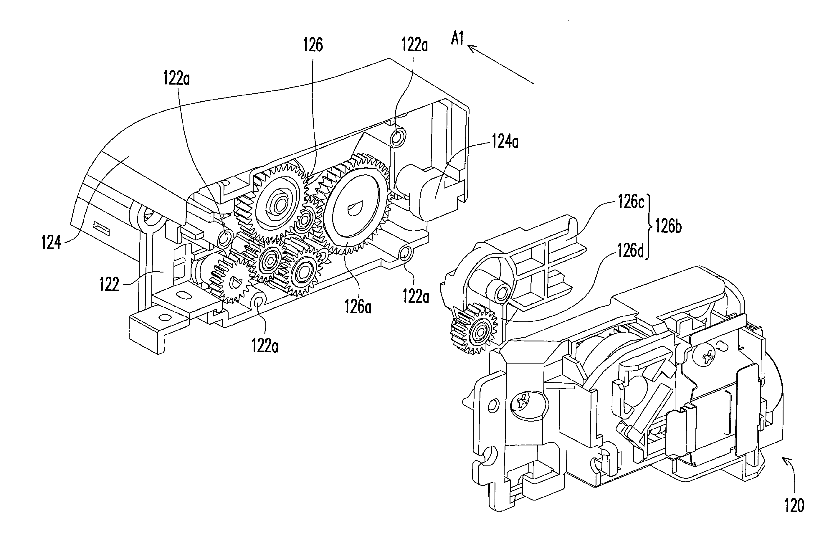
[0047]FIG. 3 is a schematic view of a media record equipment according to a first embodiment of the present invention. FIG. 4 is an exploded view of an automatic document feeder of the media record equipment in FIG. 3. FIG. 5 is a schematic view of an assembly of the automatic document feeder in FIG. 4. Referring to FIGS. 3 to 5, the media record equipment 100 includes a main body 110 and an automatic document feeder 120 disposed on the main body 110. The automatic document feeder 120 includes a frame 122, a cover 124 and a gear chain 126, wherein an end of the cover 124 is pivoted to the frame 122 and therefore the cover 124 could be open or close relative to the frame 122, and the end of the cover 124 pivoted to frame 122 has a cam 124a. The gear chain 126 disposed in the frame 122 includes a plurality of driven gears 126a and a rotating unit 126b, wherein the driven gears 126a are disposed with the first axial direction Al as a rotating axle, and the driven gears 126a engage with...

second embodiment

[0057]The second embodiment is similar to the first embodiment, and elements that are equivalent or alike use equivalent or alike references.

[0058]FIG. 8 is a partial schematic view illustrating an automatic document feeder with a cover closing according to a second embodiment. Referring to FIG. 8, the cam in the present embodiment is a shaft 124b, and the first rock arm 126c has an U-shaped opening 126f, wherein the shaft 124b is located in the U-shaped opening 126f when the cover 124 is close relative to the frame 122 (as shown in FIG. 4). FIG. 9 is a schematic view illustrating the cover of the automatic document feeder in FIG. 8 is open. Referring to FIGS. 9-10, the shaft 124b located in the U-shaped opening 126f moves relative to the rotating unit 126b along a profile of the U-shaped opening 126f, and props the U-shaped opening 126f when the cover 124 opens relative to the frame 122. The rotating unit 126b rotates about the first axial direction Al, and the driven gear 127b dis...

third embodiment

[0059]The third embodiment is similar to the above embodiments, and elements that are equivalent or alike use equivalent or alike references.

[0060]FIG. 10 is a schematic view of an automatic document feeder according to a third embodiment. Referring to FIG. 10, the difference between the present embodiment and the above two embodiments is that: the cam 124d of the present embodiment has a first tooth portion 124e, and the first rock arm 126c of the rotating unit 126b has a second tooth portion 126g, and the first tooth portion 124e engages with the second tooth portion 126g. Through the engagement between the first tooth portion 124e and the second tooth portion 126g, the rotating unit 126b rotates with the opening of the cover 124 relative to the frame 122, and the engagement between the driven gear 127b disposed on the second rock arm 126d and the driven 126a is released; therefore the jammed paper is ejected.


PUM


Abstract

An automatic document feeder and a media record equipment using the same are provided. The automatic document feeder includes a frame, a cover and a gear chain. An end of the cover pivoted to the frame has a cam. The gear chain disposed in the frame has multiple driven gears and a rotating unit. The driven gears engaged with each other rotate about a first axial direction. The rotating unit having a first rock arm contacting the cam and a second rock arm with one of the driven gears disposed thereon is capable of rotating about the first axial direction. The cam pushes the first rock arm to drive the rotating unit to rotate about the first axial direction, and then an engagement between the driven gear on the second rock arm is released by departing from another driven gear engaged therewith when the cover opens relative to the frame.

Description

CROSS-REFERENCE TO RELATED APPLICATION[0001]This application claims the priority benefit of Singapore application serial no. 201204538-1, filed on Jun. 19, 2012. The entirety of the above-mentioned patent application is hereby incorporated by reference herein and made a part of this specification.BACKGROUND OF THE INVENTION[0002]1. Field of the Disclosure[0003]The present invention is related to an automatic document feeder and a media record equipment, and more particularly, to an automatic document feeder and a media record equipment with convenience of jam releasing for a user.[0004]2. Description of Related Art[0005]Different sorts of electronic devices have been gradually developed and become necessary tools in daily lives. For example, equipments such as computers, printers, fax machines and photocopiers are configured in an office for document processing. Work efficiency of printers, photocopiers and fax machines related to paper are influenced by faculty of paper feeding.[00...

Claims


Application Information

Patent Timeline
IPC IPC(8): G03G15/00
CPCB65H3/06B65H3/0669B65H3/5223B65H5/062B65H2402/441B65H2402/46B65H2403/422B65H2403/5331B65H2403/722B65H2407/20B65H2801/39
Inventor RECINTO, MICHAEL MEDRANOVICENTE, DOMINGO JR. ABAOTOH, CHER-LEKHUANG, CHEN-FUCABRAL, HAROLD MAGTIBAY
Owner CAL COMP PRECISION SINGAPORE