Wiper apparatus

Inactive Publication Date: 2013-12-26
MITSUBA CORP
View PDF2 Cites 3 Cited by
  • Summary
  • Abstract
  • Description
  • Claims
  • Application Information

AI Technical Summary

Benefits of technology

[0007]On the other hand, according to the above described wiper apparatus described in Patent Document 2, since the housing which forms the gear part is fixed to the hollow frame with the plurality of bolts and nuts, the wiper motor can be directly fixed to the hollow frame without the intermediation of the motor bracket. Therefore, compared with the technique of Patent Document 1, since the motor bracket is not provided to the wiper apparatus described in Patent Document 2, reduction in weight of the wiper apparatus can be realized by reducing the number of bolts corresponding to the mo

Problems solved by technology

Therefore, the number of the bolts in the whole wiper apparatus is large, the operation of assembling the wiper apparatus is complex, the yield rate thereof is relatively low, and in addition, it encounters a problem that the weight of the wiper apparatus is increased by them.
Furthermore, the motor bracket is large since the motor bracket is composed of the bracket main body, the frame fixing part, and the bracket attaching part, and it encounters a pr

Method used


Image

  • Wiper apparatus
  • Wiper apparatus
  • Wiper apparatus

Examples


first embodiment

[0026]Hereinafter, the present invention will be described in detail with reference to the drawings.

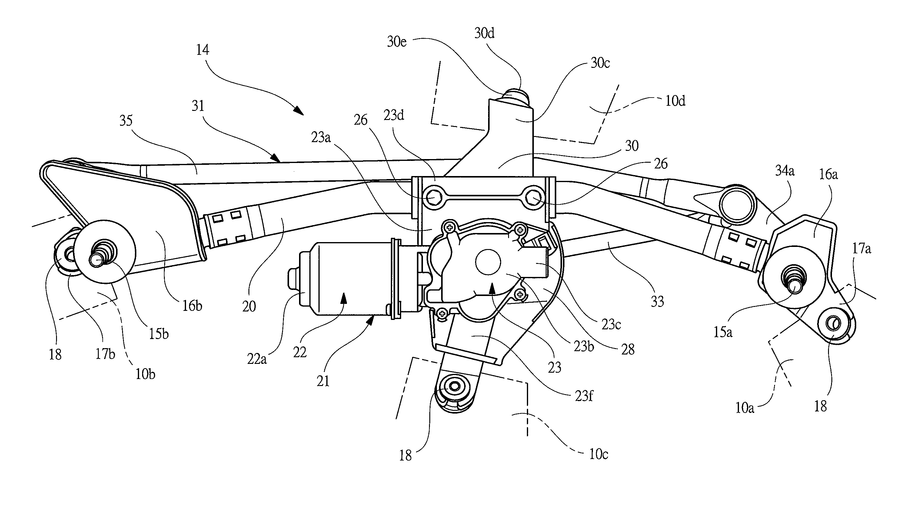
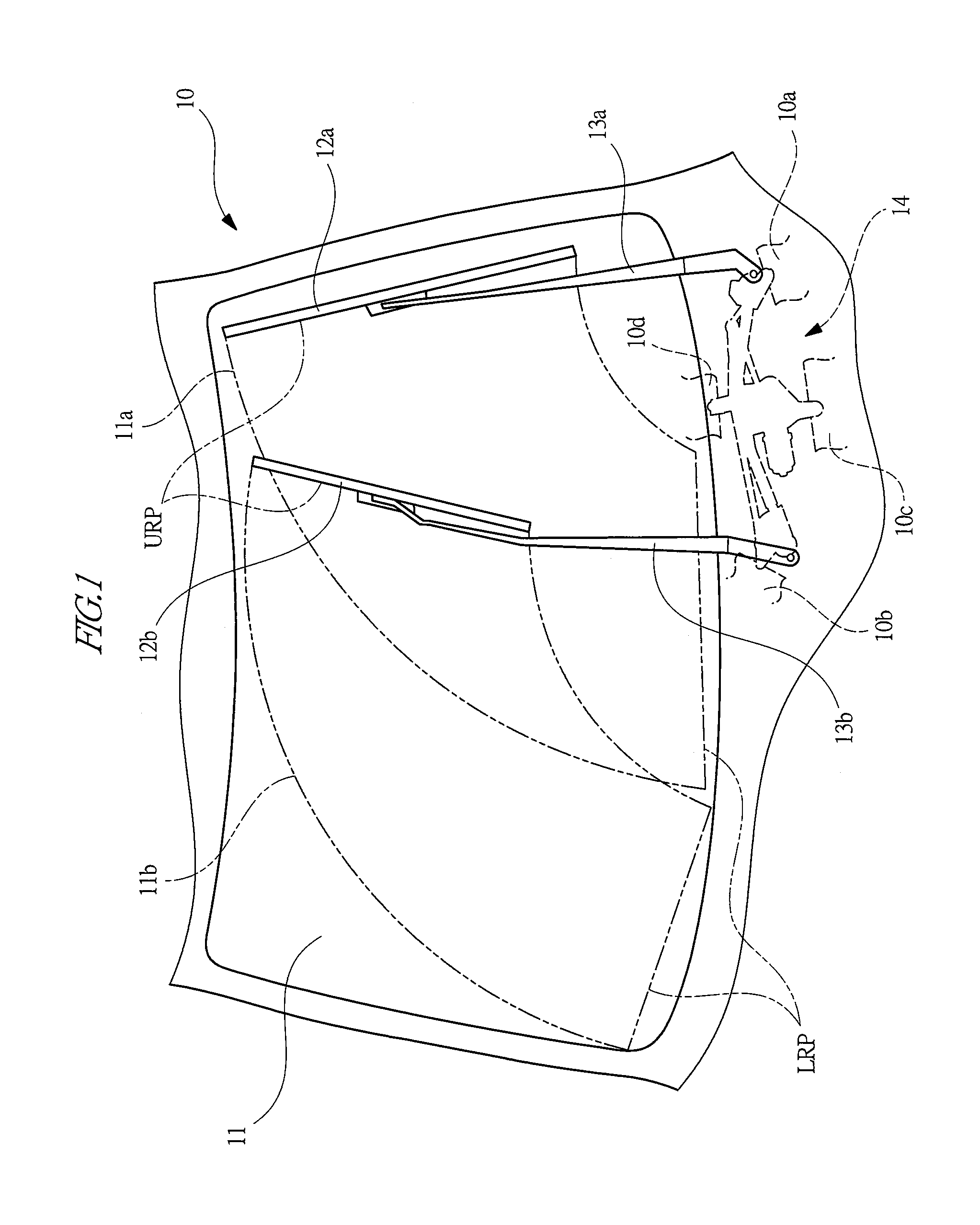
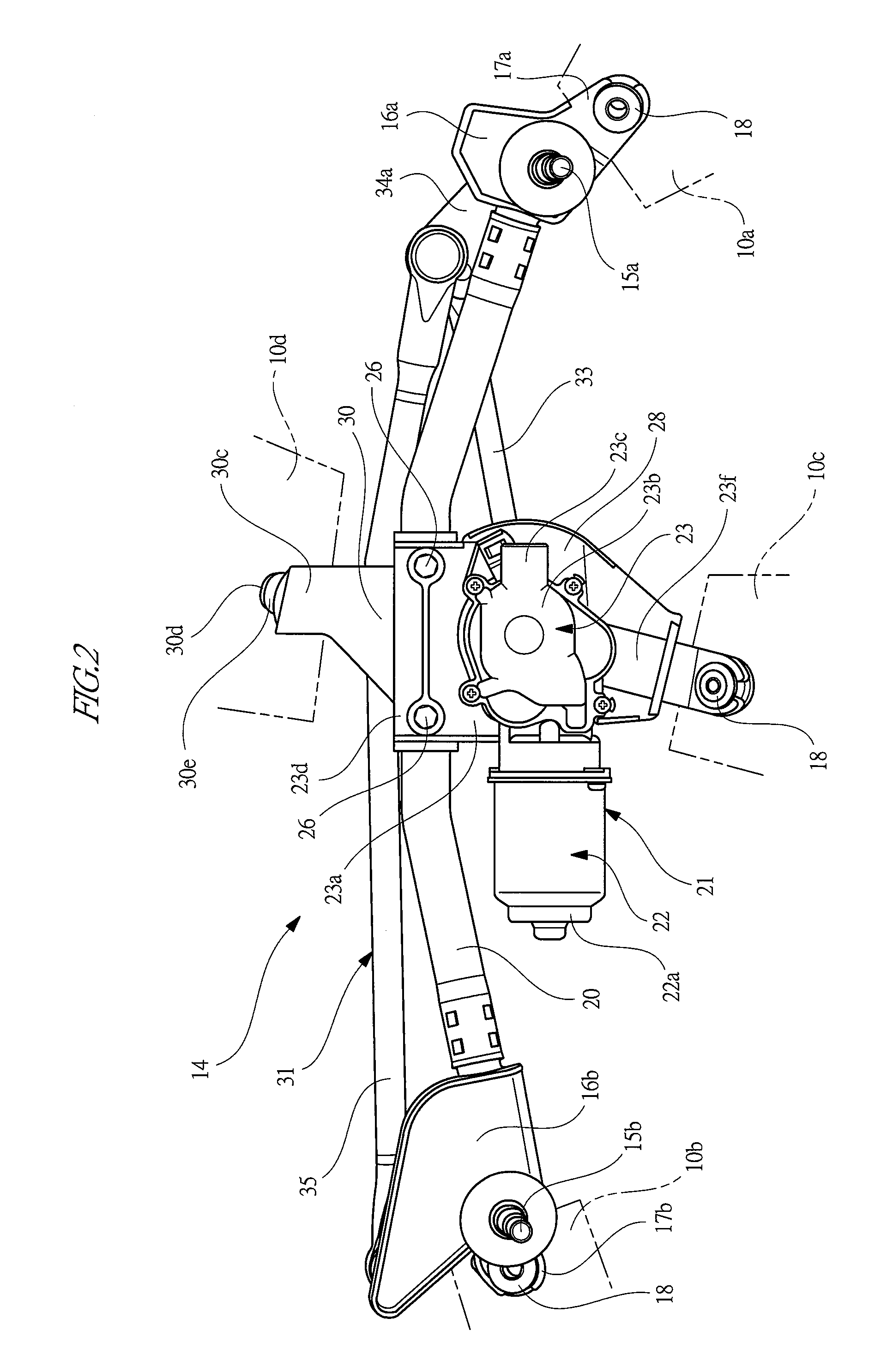
[0027]FIG. 1 is a view explaining a front side of a vehicle provided with a wiper apparatus according to the present invention, FIG. 2 is a schematic front view of the wiper apparatus seen from its front side, FIG. 3 is a schematic rear view of the wiper apparatus seen from its rear side, FIG. 4 is an enlarged perspective view of a portion including a wiper motor (a link mechanism is omitted), FIG. 5 is a view explaining an internal structure of the wiper motor, FIG. 6 is an enlarged fragmentary sectional view taken along the line A-A of FIG. 3, and FIG. 7 is a view explaining an assembling procedure of the wiper apparatus.

[0028]As shown in FIG. 1, a windshield 11 is provided to a front side portion of a vehicle 10. A driver-seat side (hereinafter simply referred to as “DR-side”) wiper blade 12a and a front passenger-seat side (hereinafter simply referred to as “AS-side”) wiper blade ...

third embodiment

[0071]A distal end side of an extending part 61 provided to the attachment bracket 60 is directed to the front-side vehicle-body panel 10c of the vehicle 10 so as to extend across the motor part 22 as well as the The insertion pin 30d provided at the distal end side of the extending part 61 is inserted and fixed to an insertion hole (not shown) provided to the front-side vehicle-body panel 10c so that the wiper apparatus 14 can be tentatively fixed to the vehicle 10. However, like an attachment bracket 60′ shown by a two-dotted chain line in the drawing, the distal end side of an extending part 61′ may be directed to the front-side vehicle-body panel 10c across the drive connecting rod 33 of the link mechanism 31.

[0072]Also in the fourth embodiment thus configured, it is possible to have advantageous effects similar to those of the above described first embodiment. In addition, in the fourth embodiment, since the second frame fixing part 30a and the first frame fixing part 23d are ...

fourth embodiment

[0076]Furthermore, the above described fourth embodiment shows the case in which the fastening bolts 26 penetrate through the frame member 20 and are connected to the fastening nuts 27 as well as the other embodiments. However, the present invention is not limited to this example, and for example, in the structure in which the wiper motor 21 is fixed at end part of the frame member 20, the fastening nuts 27 may be fixed to the interior of the frame member 20 in advance by welding or the like. In this example, since it is possible to assemble the wiper apparatus 14 without a step of positioning the fastening nuts 27 with respect to the frame member 20, the assembling workability of the wiper apparatus 14 can be further improved. Moreover, since the length of the fastening bolts 26 can be shortened, the weight of the wiper apparatus 14 can be further reduced correspondingly.

[0077]Furthermore, the above described embodiments show the cases in which the wiping pattern of the wiper appar...


PUM


Abstract

In a wiper apparatus, a gear case of a gear part is provided with a first frame fixing part which is fixed to a frame member by fastening volts and fastening nuts. An attachment bracket has a second frame fixing part which is fixed to the frame member together with the first frame fixing part by the fastening volts and the fastening nuts, and has an insertion pin which is fixed to a rear-side vehicle-body panel. A wiper motor can be fixed to the frame member together with the attachment bracket by the same fastening members, and it is possible to reduce the weight of the wiper apparatus by reducing the number of the fastening members. It is possible to enhance the productivity of the wiper apparatus by reducing the size of the attachment bracket separated as a dedicated part from the gear case.

Description

TECHNICAL FIELD OF THE INVENTION[0001]The present invention relates to a wiper apparatus for driving and swinging a wiper arm by an electric motor and wiping off substances attached on a windshield.BACKGROUND OF THE INVENTION[0002]Conventionally, a wiper apparatus is mounted on a vehicle such as an automobile. The wiper apparatus is configured to drive and swing a wiper arm to which a wiper blade is attached, and to wipe off substances such as rainwater and dust attached on a windshield. The wiper apparatus is provided with a pivot shaft to which an end part of the wiper arm is fixed, and with an electric motor which drives the pivot shaft. When an operation switch in the interior of the vehicle is operated, the electric motor is driven, and as a result, the wiper blade is configured to be swung via the pivot shaft.[0003]A wiper apparatus provided with wiper arms in a driver-seat side and a front passenger-seat side, respectively, is provided with pivot shafts corresponding to the r...

Claims


Application Information

Patent Timeline
IPC IPC(8): B60S1/06
CPCB60S1/0427B60S1/0433B60S1/166
Inventor IIZUKA, TAKAMICHIKUWABARA, ATSUHIRO
Owner MITSUBA CORP
Why Eureka
Try Eureka