Roller lifter for internal combustion engine

Active Publication Date: 2013-12-26
OTICS CORP
View PDF4 Cites 18 Cited by
  • Summary
  • Abstract
  • Description
  • Claims
  • Application Information

AI Technical Summary

Benefits of technology

[0019]The anti-rotation retainer in the roller lifter for internal combustion engines extends radially outward from the sliding surface of the lifter body. Therefore, the lifter body need not be cut off largely to form the anti-rotation retainer. The lifter body can have higher rigidity accordingly, so that the circularity accuracy of the sliding surface can be maintained when the axial support pin is mechanically fastened to the support portions.
[0020]The sliding surface of the lifter body is formed on the front side and the rear side in the sliding direction of the anti-rotation retainer. Therefore, the

Problems solved by technology

This may result in large cocking (wobbling) in the cylinder when

Method used


Image

  • Roller lifter for internal combustion engine
  • Roller lifter for internal combustion engine
  • Roller lifter for internal combustion engine

Examples


Example

Example 1

[0040]Specific embodiments of the roller lifter for internal combustion engines will be described below with reference to FIGS. 1 to 5.

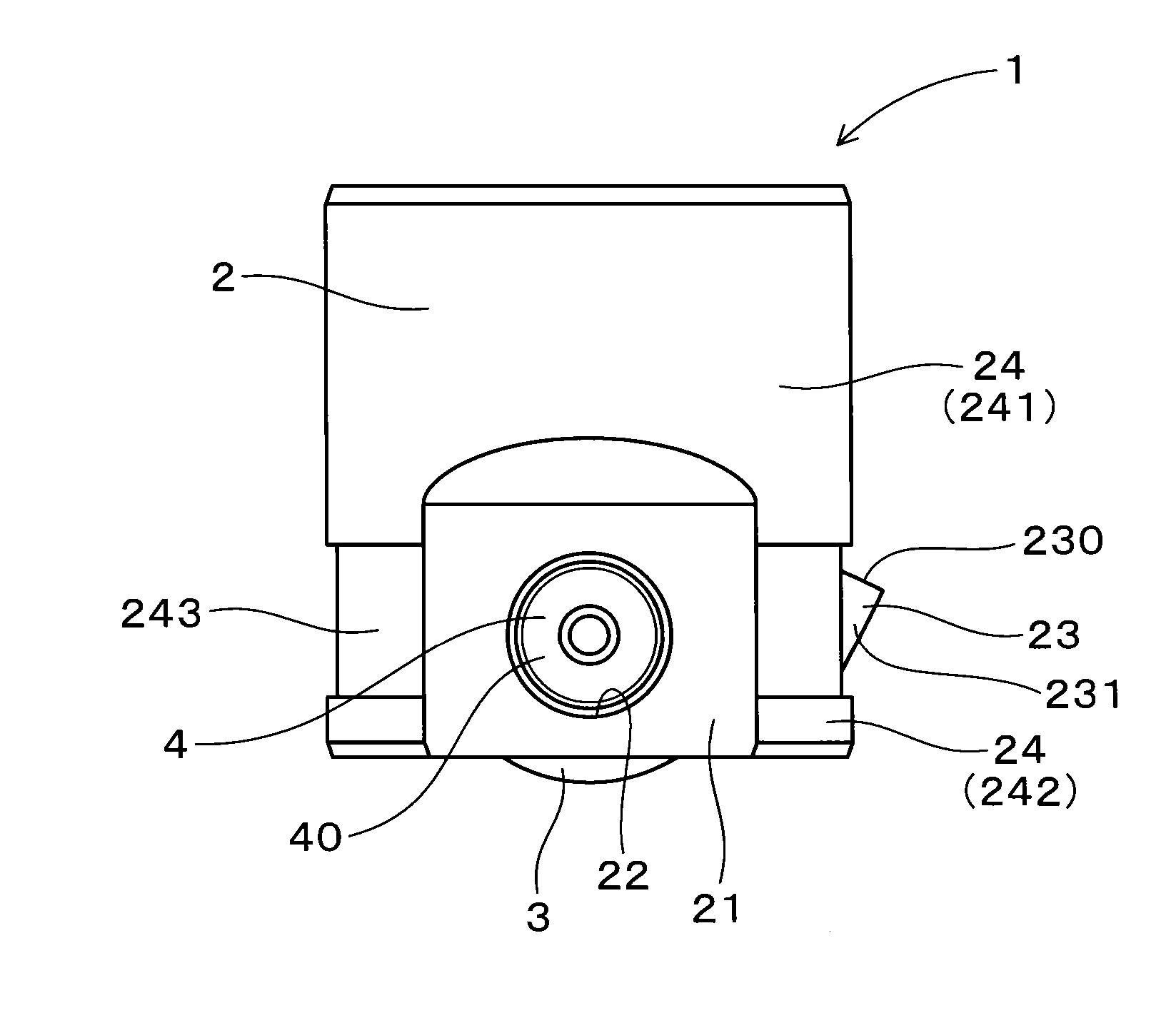
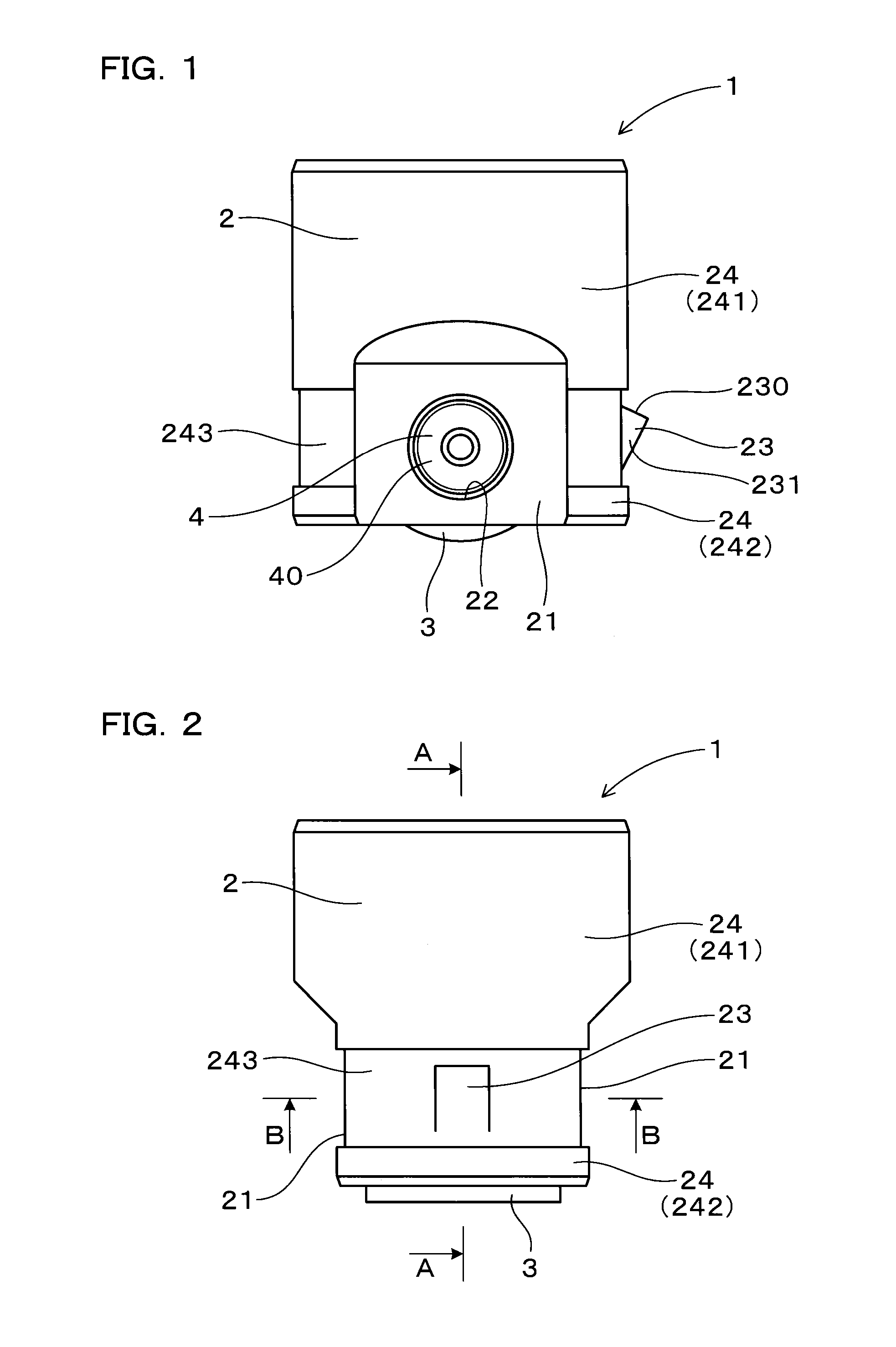
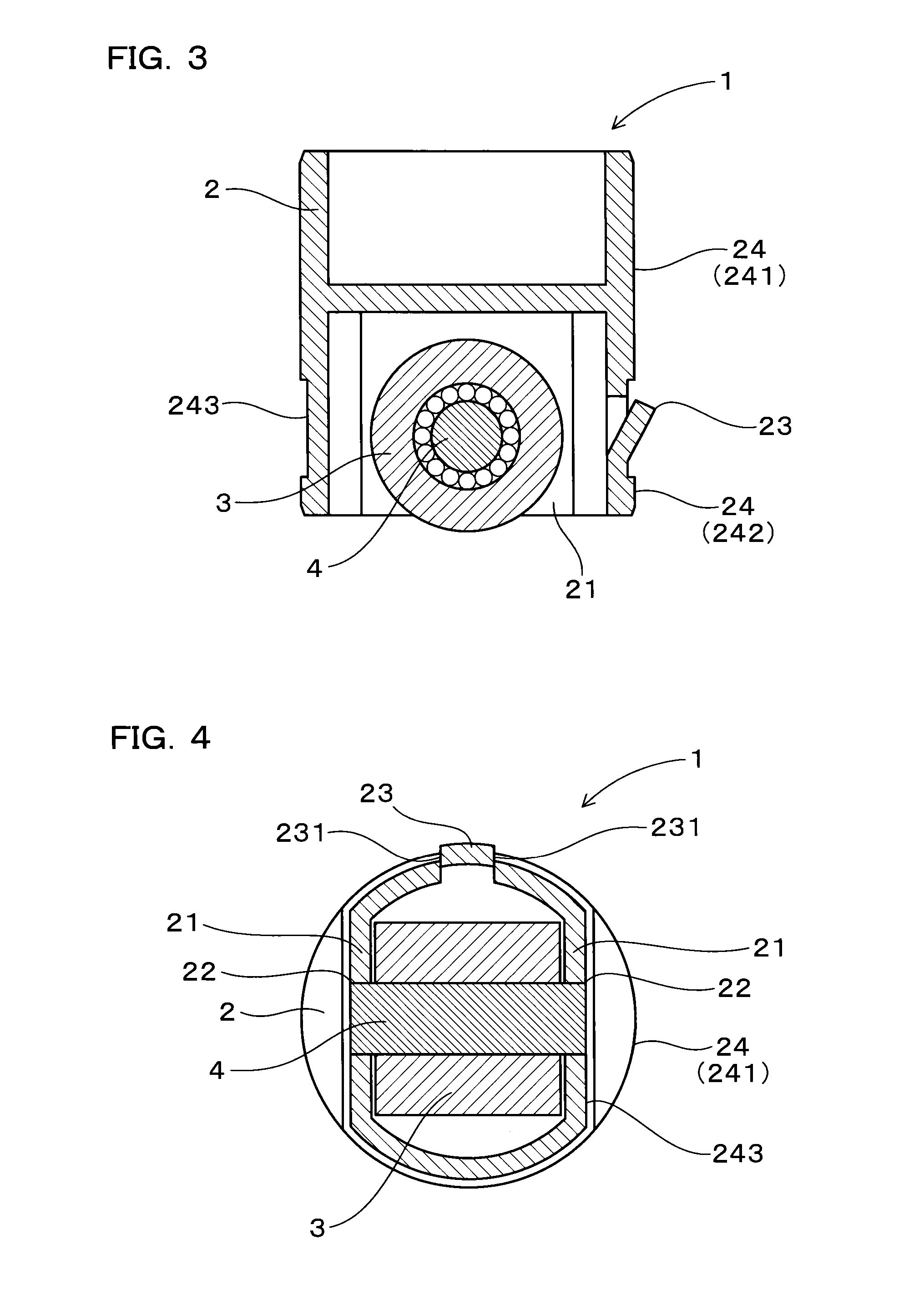
[0041]The roller lifter 1 for internal combustion engines of this embodiment includes a cylindrical lifter body 2 having a sliding surface 24 on its outer circumferential surface that slides on an inner wall 51 of a cylinder 5, and a roller 3 rotatably attached to the lifter body 2 with an axial support pin 4 and making contact with a rotating cam lobe 6, as shown in FIGS. 1 and 5.

[0042]The lifter body 2 has a pair of support portions 21 for supporting the axial support pin 4.

[0043]Both ends 40 of the axial support pin 4 are inserted in support holes 22 formed in the pair of support portions 21 and mechanically fastened thereto.

[0044]The lifter body 2 has an anti-rotation retainer 23 extending radially outward from the sliding surface 24. The sliding surface 24 is formed both on the front and rear sides in the sliding direction of the anti-r...

Example

Example 2

[0075]This embodiment is an example in which the roller lifter 1 is used as a valve lifter 70B in a valve gear 7B of a reciprocal engine.

[0076]The roller lifter 1 itself is configured the same as the roller lifter 1 of Embodiment 1.

[0077]The valve lifter 70B in the valve gear 7B is configured to slide inside a cylinder 5 arranged in a cylinder head 73 of the reciprocal engine, as the roller 3 is rotated by the rotating valve gear cam lobe 6 formed on a cam shaft 61 of the reciprocal engine, as shown in FIG. 6.

[0078]The valve lifter 70B abuts on a stem distal end 732 of a valve 730 in the reciprocal engine, and is arranged slidable up and down inside the cylinder 5 such as to open and close the valve 730 disposed to open and close an intake / exhaust port (intake port or exhaust port) 733.

[0079]An abutting portion 25 is configured to abut on the stem distal end 732 of the valve 730.

[0080]A retainer 77 is secured to the outer circumference of a stem part 731 of the valve 730. A...

Example

[0081]The rest is the same as Embodiment 1, with similar advantageous effects.


PUM


Abstract

A roller lifter for internal combustion engines is provided, which has higher rigidity of the lifter body, prevents cocking in the cylinder, and can achieve a size reduction. The roller lifter includes a cylindrical lifter body having a sliding surface on an outer circumferential surface thereof and a roller rotatably attached to the lifter body via an axial support pin and making contact with a rotating cam lobe. The lifter body includes a pair of support portions supporting the axial support pin. The axial support pin is mechanically fastened to the pair of support portions, with both ends thereof inserted in support holes formed in the support portions. The lifter body includes an anti-rotation retainer extending radially outward from the sliding surface. The sliding surface is formed on both front and rear sides in the sliding direction of the anti-rotation retainer.

Description

[0001]CROSS-REFERENCE[0002]This application claims priority to Japanese patent application no. 2012-138596 filed on Jun. 20, 2012, the contents of which are entirely incorporated herein by reference.FIELD OF THE INVENTION[0003]The present invention relates to a roller lifter for internal combustion engines used in car engines or the like.BACKGROUND ART[0004]There are known pump lifters used for fuel supply pumps or valve lifters used for valve gears in internal combustion engines such as car engines or the like.[0005]Some of these lifters include a roller at a portion directly contacting a cam lobe provided in fuel supply pumps or valve gear to reduce friction resistance against the cam lobe and to improve wear resistance of the surface contacting the cam lobe (hereinafter referred to as “roller lifter 9”).[0006]The roller lifter 9 is configured, as shown in FIG. 12, with a roller 93 attached to a lifter body 92 having a sliding surface 924 that slides on the inner wall of a cylinde...

Claims


Application Information

Patent Timeline
IPC IPC(8): F01L1/14
CPCF01L1/14F02M59/102F01L2305/00F01L2305/02F01L2307/00F01L1/143
Inventor FUJII, HIROKIMASEGI, KIYOSHI
Owner OTICS CORP
Why Eureka
Try Eureka