Plasma processing apparatus

a processing apparatus and plasma technology, applied in the direction of electrical apparatus, basic electric elements, electric discharge tubes, etc., can solve the problems of unbalanced plasma distribution, electrode or plasma distribution on the target object, etc., to improve the uniformity of process characteristics, improve performance and the degree of freedom, and improve the uniformity of plasma density distribution

Inactive Publication Date: 2013-12-26
TOKYO ELECTRON LTD
View PDF6 Cites 6 Cited by
  • Summary
  • Abstract
  • Description
  • Claims
  • Application Information

AI Technical Summary

Benefits of technology

[0012]In order to solve the conventional problems described above, the present disclosure provides a plasma processing apparatus and a plasma processing method capable of improving uniformity of plasma density distribution and process characteristics by greatly improving performance and the degree of freedom for controlling the plasma density distribution.
[0023]When the second conductor is rotated at a constant speed in the azimuthal direction of the high frequency electrode during the plasma process, it is possible to achieve uniformity in distribution of sheath electric field intensity, distribution of plasma density or process characteristics in its diametrical direction as well as in the azimuthal direction.
[0029]As described above, in accordance with the plasma processing apparatus of the present disclosure, it is possible to improve uniformity of plasma density distribution by greatly improving performance and the degree of freedom for controlling the plasma density distribution by the above-described configurations and operations. Further, in accordance with the plasma processing method of the present disclosure, it is possible to improve uniformity of process characteristics by the above-described configurations and operations.

Problems solved by technology

In this case, the plasma distribution on the high frequency electrode or the plasma distribution on the target object has an unbalance around a position starting from a position of the first connecting portion of the first conductor in a two-dimensional direction (particularly, in an azimuthal direction).

Method used


Image

  • Plasma processing apparatus
  • Plasma processing apparatus
  • Plasma processing apparatus

Examples


first embodiment

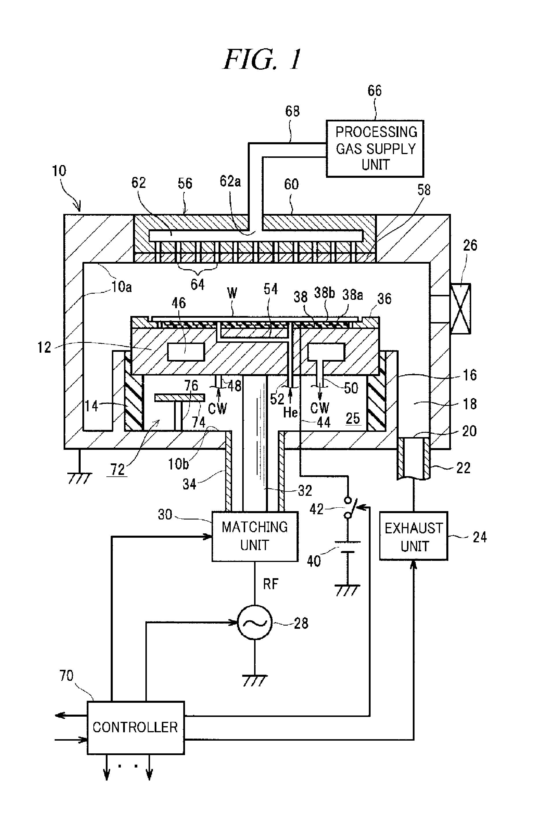
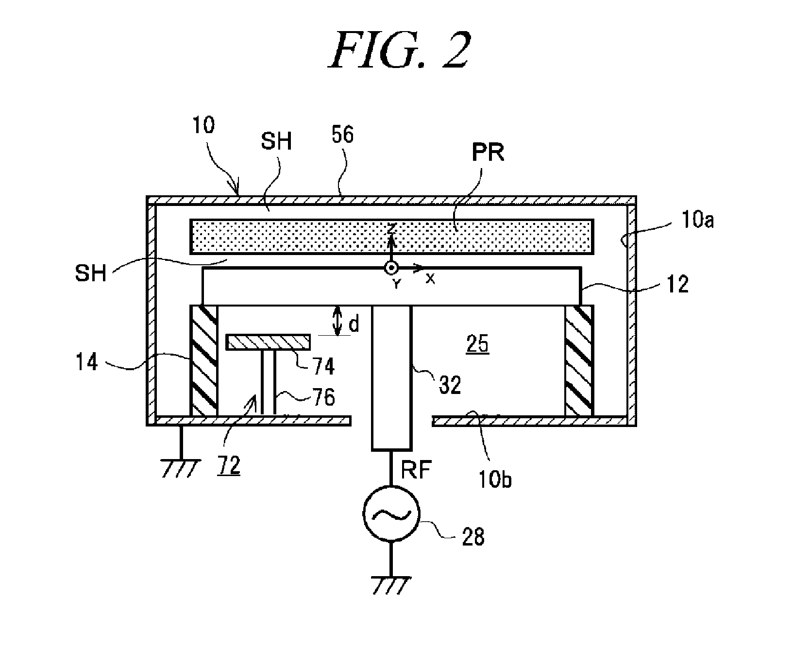
[0087]The plasma density distribution controller 72 in accordance with a first embodiment includes a conductive plate (first conductor) 74 which is placed substantially parallel (horizontally) under the rear surface of the susceptor 12 at a certain position to face the susceptor 12 and a conductive rod (second conductor) 76 which supports the conductive plate 74 upward and is electrically grounded. Both the conductive plate 74 and the conductive rod 76 are made of conductive metal such as copper or aluminum.

[0088]To be more specific, the conductive plate 74 is extended in a circular arc shape along a circumference direction of the power feed rod 32 or along an inner wall of the cylindrical insulating member 14, and is distanced from the rear surface of the susceptor 12 at a certain distance d. The conductive rod 76 is uprightly extended from the conductive plate 74. An upper end (first connecting portion) of the conductive rod 76 is fixed to a certain portion of a bottom surface of ...

second embodiment

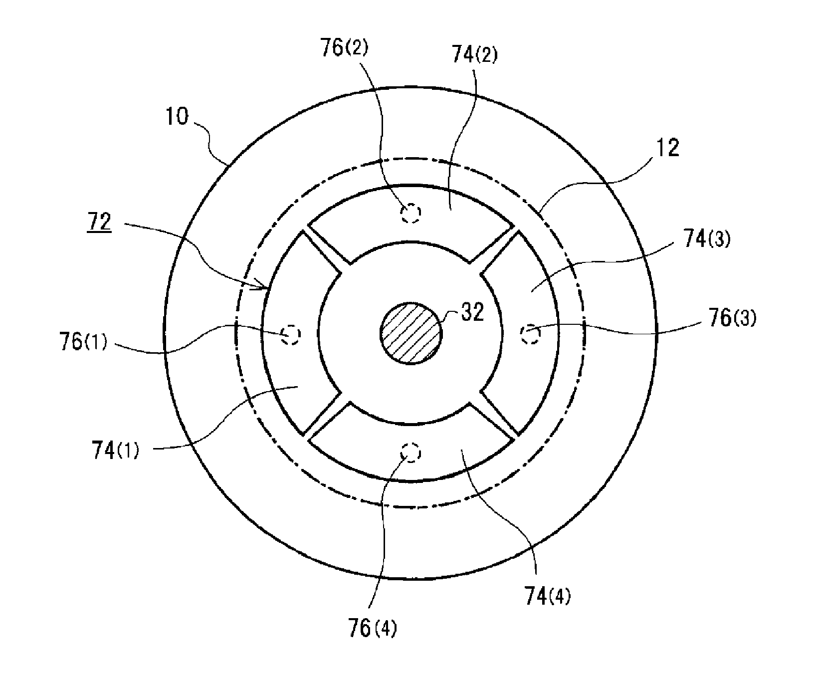
[0113]In a second embodiment which is characteristically or developmentally modified from the layout of FIG. 9 in the first embodiment, a plurality of pairs of conductive rods 76(1), 76(2), . . . can be equi-spaced around a circumference (about 360°) in an azimuthal direction.

[0114]For example, in case of a three-pair type as illustrated in FIG. 10, three conductive rods 76(1), 76(2), and 76(3) are equi-spaced at about 120° around the power feed rod 32. In case of a four-pair type as illustrated in FIG. 11, four conductive rods 76(1), 76(2), 76(3), and 76(4) are equi-spaced at about 90° around the power feed rod 32.

[0115]FIG. 12 shows etching rate distribution obtained by the plasma etching apparatus (second embodiment apparatus) shown in FIG. 1 including the plasma density distribution controller 72 (three-pair type of FIG. 10) in accordance with the second embodiment in the first experimental example (recipe A) as compared to etching rate distribution obtained by the comparative e...


PUM

PropertyMeasurementUnit
frequencyaaaaaaaaaa
diameteraaaaaaaaaa
radial distanceaaaaaaaaaa

Abstract

A plasma processing apparatus includes at least one asymmetry member that causes a non-uniformity of plasma density around the high frequency electrode; and a plasma density distribution controller that is arranged depending on arrangement of the at least one asymmetry member to suppress the non-uniformity of plasma density around the high frequency electrode in the azimuthal direction. The plasma density distribution controller includes a first conductor which has first and second surfaces facing opposite directions to each other and is electrically connected with the rear surface of the high frequency electrode with respect to the first high frequency power; and a second conductor which includes a first connecting portion(s) electrically connected with a portion of the second surface of the first conductor and a second connecting portion electrically connected with a conductive grounding member electrically grounded around the high frequency electrode with respect to the first high frequency power.

Description

CROSS-REFERENCE TO RELATED APPLICATION[0001]This is a divisional application of U.S. patent application Ser. No. 12 / 748,601, filed on Mar. 29, 2010 which claims the benefit of Japanese Patent Application No. 2009-082567 filed on Mar. 30, 2009 and U.S. Provisional Application Ser. No. 61 / 186,912, filed on Jun. 15, 2009, the entire disclosures of which are incorporated herein by reference.FIELD OF THE INVENTION[0002]The present disclosure relates to a technique of performing a plasma process on a target object within a processing chamber including a high-frequency electrode. In particular, the present disclosure relates to a capacitively coupled plasma processing apparatus for generating plasma by a high-frequency discharge generated by applying a high frequency power to a high-frequency electrode.BACKGROUND OF THE INVENTION[0003]In a microprocessing or a processing such as etching, deposition, oxidation, and sputtering for manufacturing a semiconductor device or a FPD (Flat Panel Dis...

Claims


Application Information

Patent Timeline
Patent Type & Authority Applications(United States)
IPC IPC(8): H01J37/32
CPCH01J37/32623H01J37/32091H01J37/32541H01J37/3255H01J37/32697
Inventor YAMAZAWA, YOHEIOKUNISHI, NAOHIKOMISAWA, HIRONOBUSOETA, HIDEHITO
Owner TOKYO ELECTRON LTD
Why Eureka
Try Eureka