Rotary solenoid

a solenoid and rotary technology, applied in the direction of dynamo-electric machines, electrical apparatus, magnetic bodies, etc., can solve the problem of limiting the output torque of the solenoid, and achieve the effect of low saturation flux density

Active Publication Date: 2013-12-26
JOHNSON ELECTRIC SA
View PDF0 Cites 8 Cited by
  • Summary
  • Abstract
  • Description
  • Claims
  • Application Information

AI Technical Summary

Benefits of technology

[0008]In embodiment of the present invention, as the rotary solenoid has three stator poles and three rotor poles, the interaction area between the stator and the rotor is relatively big. In addition, due to the flux in the stator pole wound by the coil is divided into two parts at the other two stator poles, the saturation flux density is therefore low. There features benefit the output torque of the rotor.

Problems solved by technology

All these features would limit the output torque of the solenoid.

Method used


Image

  • Rotary solenoid
  • Rotary solenoid
  • Rotary solenoid

Examples


Embodiment Construction

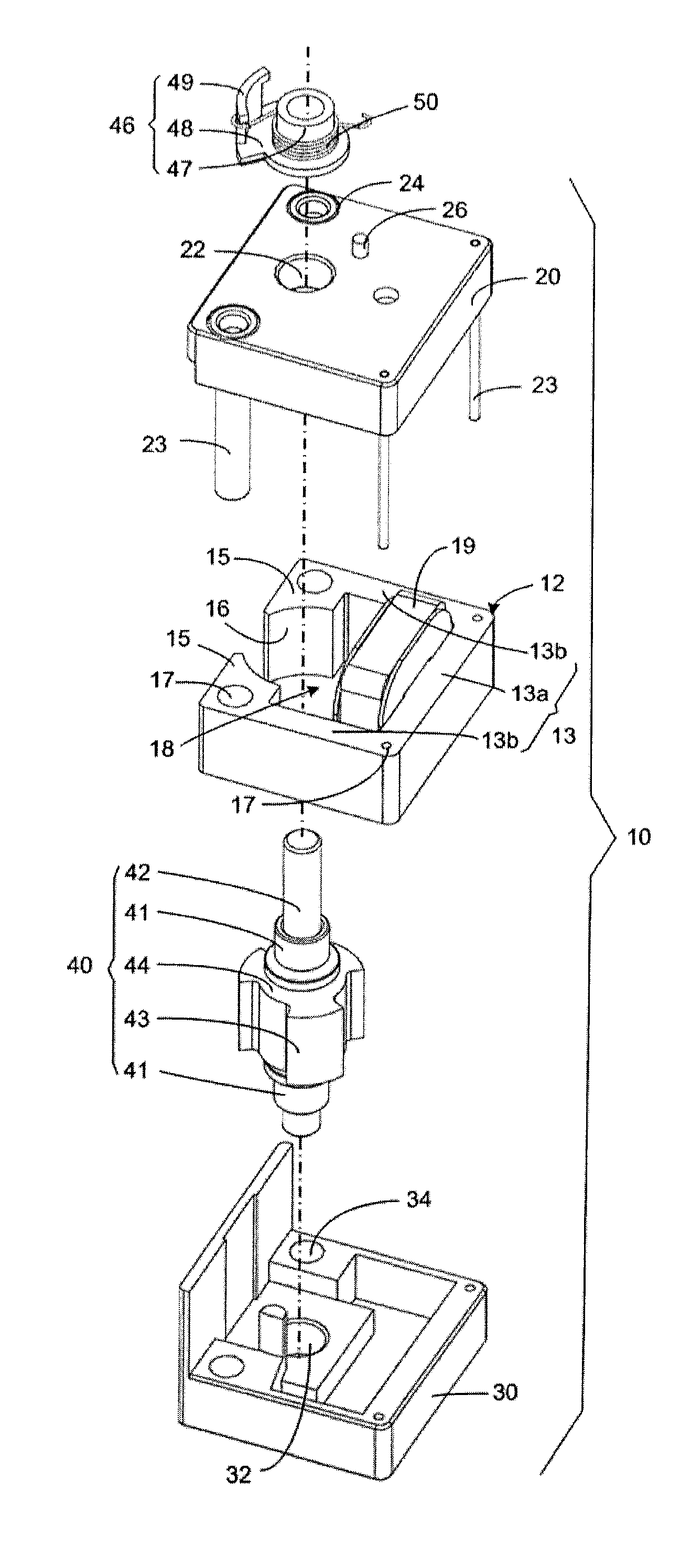
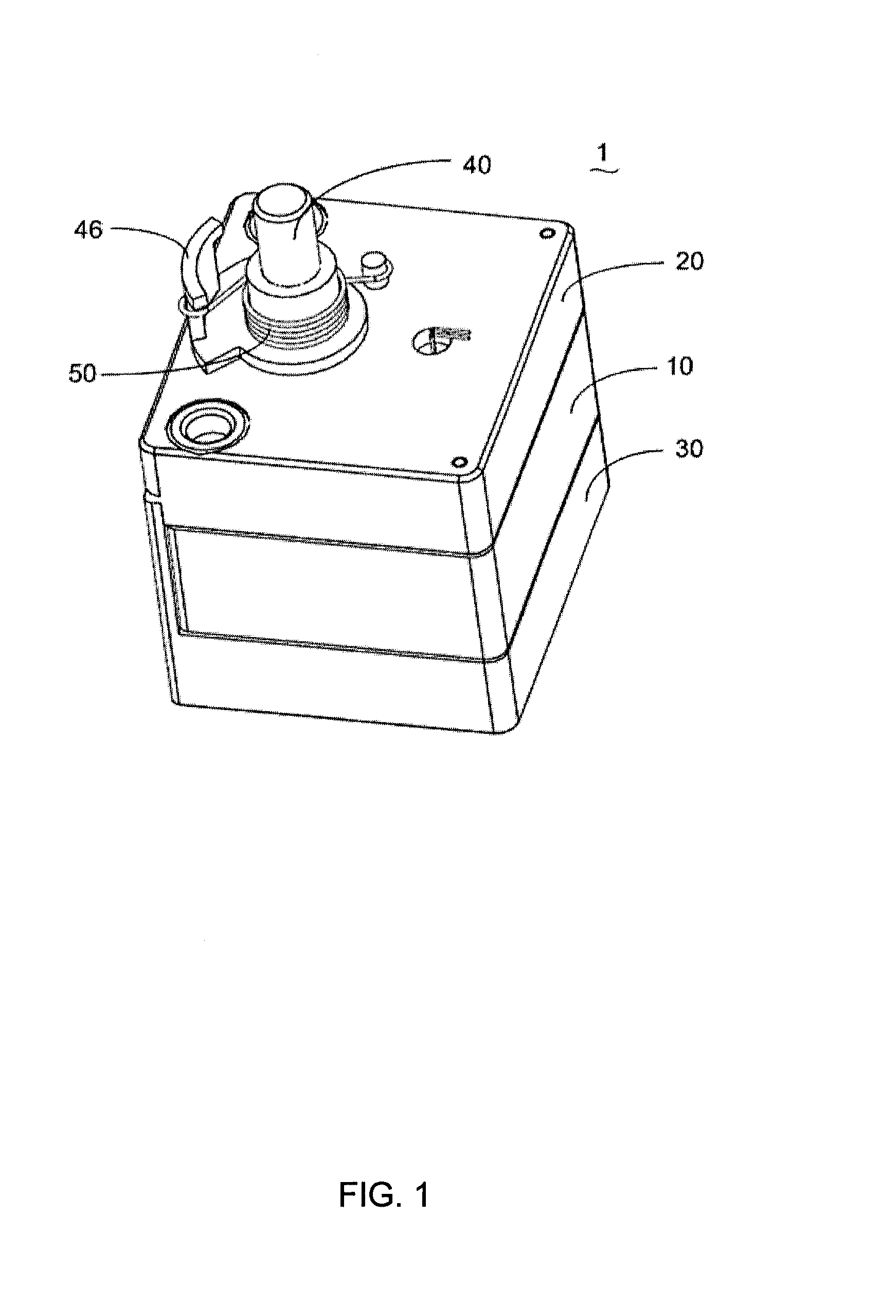
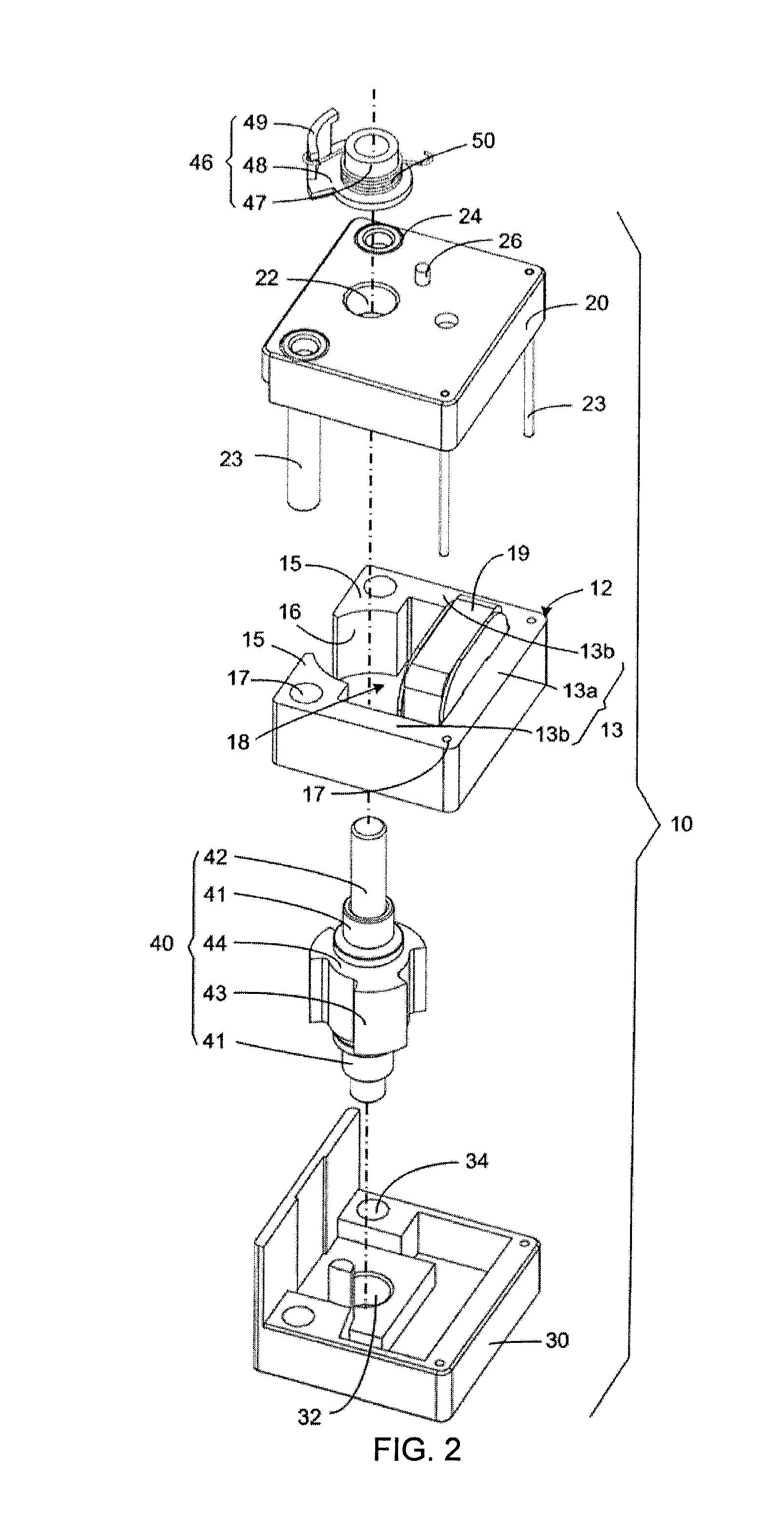
[0016]Referring to FIGS. 1 and 2, a rotary solenoid 1 in accordance with an embodiment of the present invention can be used to drive a device, such as a valve (not shown), to change between two different states. The rotary solenoid 1 includes a stator 10, a rotor 40 rotatably housed in the stator 10, and a torsion spring 50.

[0017]The stator 10 includes a substantially E-shaped stator core 12, a coil 19, a first cover 20, and a second cover 30. The stator core 12 includes an armature 13, a first stator pole 14 (shown in FIG. 4), and two second stator poles 15. The armature 13 includes an elongated central portion 13a and two end portion 13b parallel to each other and extending from two opposing ends of the central portion 13a. The first stator pole 14 protrudes perpendicularly from the middle of the central portion 13a. The two second stator poles 15 protrude from the distal ends of the two end portions 13b, extending towards each other. End surfaces 16 of the first and second stator...


PUM

PropertyMeasurementUnit
angleaaaaaaaaaa
angleaaaaaaaaaa
angleaaaaaaaaaa

Abstract

A rotary solenoid (1) includes a stator (10), a rotor (40), and a torsion spring (50) connected between the stator (10) and the rotor (40). The stator (10) includes an armature (13) having three stator poles (14, 15) cooperatively defining a substantially cylindrical space (18) and a coil (19) wound about one of the stator poles (14). The rotor (40) includes a shaft (42) rotatably assembled to the stator (10) and a rotor core (44) fixed to the shaft (42) and received in the cylindrical space (18). The rotor core (44) has three rotor poles (43) corresponding to the stator poles (14, 15). The rotor (40) stays at a first position under the force of the torsion spring (50) and rotates to a second position under the force of the torsion spring (50) and the magnetic force of stator (10) when the coil (19) is powered.

Description

CROSS REFERENCE TO RELATED APPLICATIONS[0001]This non-provisional patent application claims priority under 35 U.S.C. §119(a) from Patent Application No. 201210208393.6 filed in The People's Republic of China on Jun. 21, 2012.FIELD OF THE INVENTION[0002]The present invention relates to rotary solenoids, and particularly, to a rotary solenoid having large torque output.BACKGROUND OF THE INVENTION[0003]A rotary solenoid includes a stator and a rotor. The stator includes a rectangular iron core with two stator poles extending from two opposing inner surfaces thereof and two coils wound about the two stator poles. The rotor is located between the two stator poles and includes two rotor poles extending in opposing direction. During operation, when the two coils are activated, the two stator poles generate a magnetic field that interacts with and attracts the two rotor poles, thereby driving the rotor to rotate. However, as there are two coils wound around the two stator poles, saturation ...

Claims


Application Information

Patent Timeline
Patent Type & Authority Applications(United States)
IPC IPC(8): H01F7/121
CPCH01F7/121H02K26/00H02K33/02
Inventor LI, YUEJIANG, MAO XIONGZHOU, CHUI YOUGAN, JIN YUNYUAN, XIAO MEICHEN, YING
Owner JOHNSON ELECTRIC SA
Why Eureka
Try Eureka