Rotation speed raising device for permanent magnetic motor

A permanent magnet motor technology, applied in the direction of a single motor speed/torque control, electronic commutator, etc., can solve the problems of lower armature speed Ω, poor output power efficiency, etc.

Inactive Publication Date: 2003-08-20
许俊甫
View PDF0 Cites 9 Cited by
  • Summary
  • Abstract
  • Description
  • Claims
  • Application Information

AI Technical Summary

Problems solved by technology

[0015] Among them, the square value of the armature current I×coil impedance=the power loss of the motor. Therefore, if the torque of the motor is increased by increasing the current, the motor will inevitably increase the power loss P of the stator coil by the square value. Heat is generated in the wire resistance of the coil, and the physical phenomenon of the metal coil also increases the impedance of the coil correspondingly due to the increase in heat. In the vicious cycle, the motor will become a phenomenon of high temperature and poor output power efficiency.
[0016] The stator part of the existing motor is a single coil winding method, and its counter electromotive force constant K E value and torque constant K T The values ​​are all constant, so its K T value and K E If the value is designed at a higher value, the armature speed Ω will be reduced in proportion

Method used


Image

  • Rotation speed raising device for permanent magnetic motor
  • Rotation speed raising device for permanent magnetic motor
  • Rotation speed raising device for permanent magnetic motor

Examples


Embodiment Construction

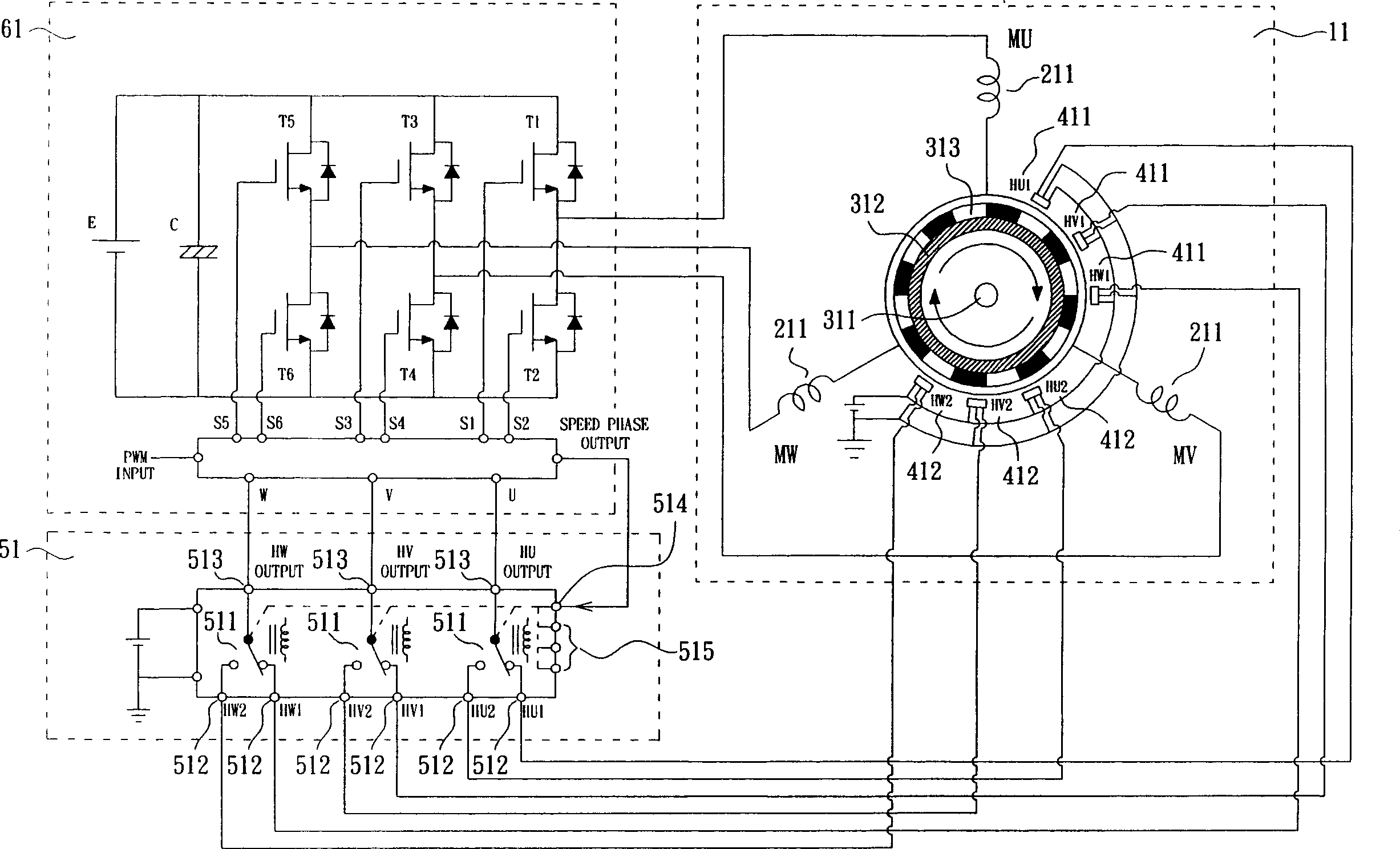
[0026] exist figure 1 , 2 , 3A, 3B to Figure 5A , 5B Among them, the present invention is a device that can increase the speed of a permanent magnet motor, which includes:

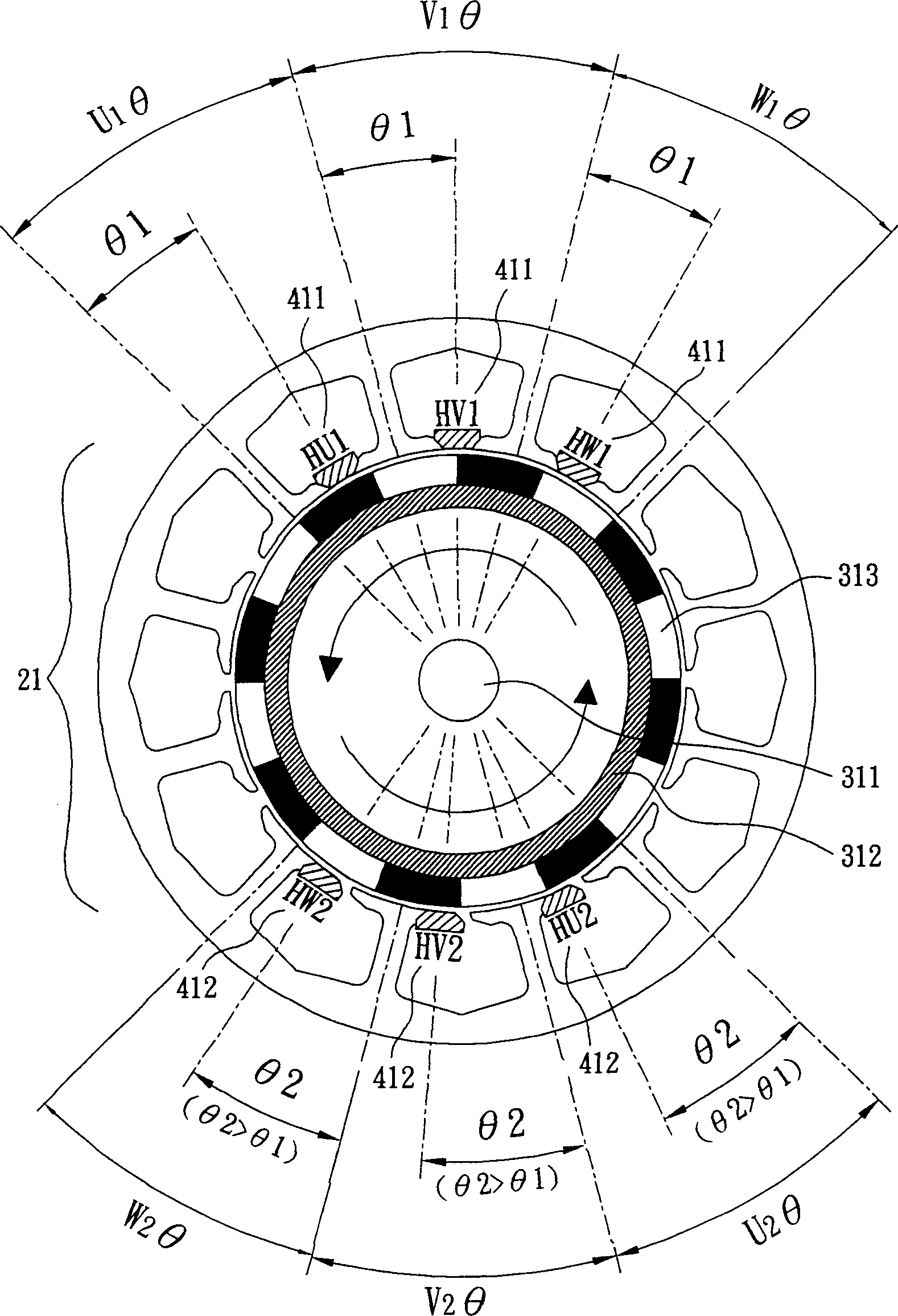
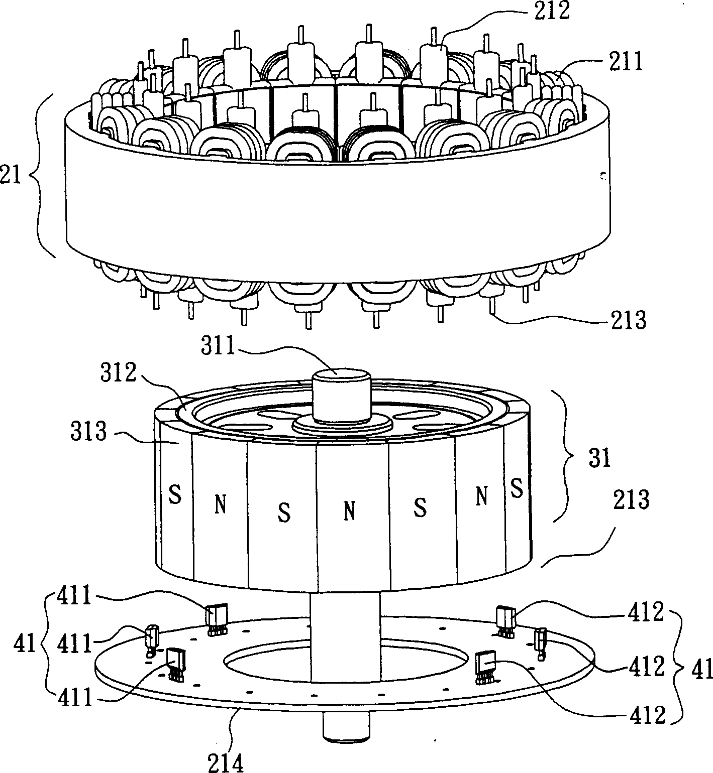
[0027] A permanent magnet motor 11, which includes a stator part 21 for the excitation coil 211 of the winding type. The stator part 21 also has a slot seat 212, a positioning device 213, a circuit board 214, etc., and multiple sets of magnetic sensors can be provided. 41 The fixed device also includes a permanent magnet rotor part 31, which contains a rotating rotor with permanent magnets. The rotor part 31 is pivotally connected to the stator part 21 with a rotating shaft 311, and corresponds to the stator part 21, and the armature reacts to rotate magnetically ; There is also a motor drive control circuit 61 for controlling the permanent magnet motor 11.

[0028] A plurality of sets of magnetic sensors 41 are arranged on the stator part 21 at various angles, and sense the rotation changes of the pe...


PUM


Abstract

The rotation speed raising device for permanent magnetic motor includes several magnetic sensors set inside the permanent magnetic motor to sense the magnetic pole conversion of the permanent magnetsin the rotor. One of the magnetic sensors makes the stator and the permanent magnetic rotor produce armature reaction with relatively strong armature air gap magnetic flux density, while the others make the motor controlled in the effect similar to weak magnetic control resulting in weak armature air gap magnetic flux density, lowered torque constant KT of the motor and increased rotation speed of the rotor. The said device makes it possible to design motor in relatively high torque constant Kt and when high rotation speed is required, the magnetic sensing selection circuit is made to output signal to produce effect similar to weak magnetic control.

Description

technical field [0001] The present invention relates to a device capable of increasing the rotational speed of a permanent magnet motor, in particular to a permanent magnet motor. The difference in transmission time and the value of the motor torque constant KT of different strengths cause the same motor to produce various motor speeds. Background technique [0002] As we all know, to manufacture a motor with high operating efficiency often needs to be designed with an appropriate torque constant K depending on its operating range. T value, as described by the following formula: [0003] E=K E K E = B D L Z / 2 [0004] T=K T K T = B D L Z / 2 [0005] in, [0006] E: Back EMF voltage (Volt) T: Output torque (N-m) [0007] K E : Back EMF constant K T : Torque constant [0008] Ω: armature speed (red / sec) Ia: armature current (Ampere) [0009] B: Air gap magnetic flux density (Gauss) D: Armature outer diameter (cm) [0010] L: Lamination thic...

Claims


Application Information

Patent Timeline
IPC IPC(8): H02P6/08H02P6/17
Inventor 许俊甫
Owner 许俊甫
Why Eureka
Try Eureka