Wire winding device and method for manufacturing same

a wire wound and wire technology, applied in the direction of transformer/inductance details, basic electric elements, coils, etc., can solve the problems of insufficient prevention of magnetic flux passage preventing action, inability to prevent b>15/b> sufficiently, and inability to reduce the effect of dielectric strength and/or physical strength, so as to minimize the penetration of magnetic flux, and reduce the effect of heat generation

Inactive Publication Date: 2013-12-26
MORI RYUTARO
View PDF9 Cites 3 Cited by
  • Summary
  • Abstract
  • Description
  • Claims
  • Application Information

AI Technical Summary

Benefits of technology

The present invention provides a wire wound device with efficient and steady performance. This is achieved by using a diamagnetic material for the inter-layer insulation that reduces magnetic flux penetration between neighboring conductors while also effectively removing any excess heat from within the device.

Problems solved by technology

The technical problem addressed in this patent relates to improving the efficiency and minimizing loss in wire wound devices of varying sizes, particularly in cases where the distance between neighboring conductor parts is too close. Previous solutions involving increased winding density have proven effective, but they come at the cost of reduced flexibility and stability during operation. Additionally, conventional methods utilizing insulation coated electrical wires face issues related to incomplete prevention of magnetic flux penetration and potential degradation of mechanical properties upon insertion of a magnetic core.

Method used


Image

  • Wire winding device and method for manufacturing same
  • Wire winding device and method for manufacturing same
  • Wire winding device and method for manufacturing same

Examples


Embodiment Construction

[0080]Hereinafter, some preferred embodiments of a wire wound device and a method for manufacturing the same according to the present invention will be described in detail, with reference to the accompanying drawings.

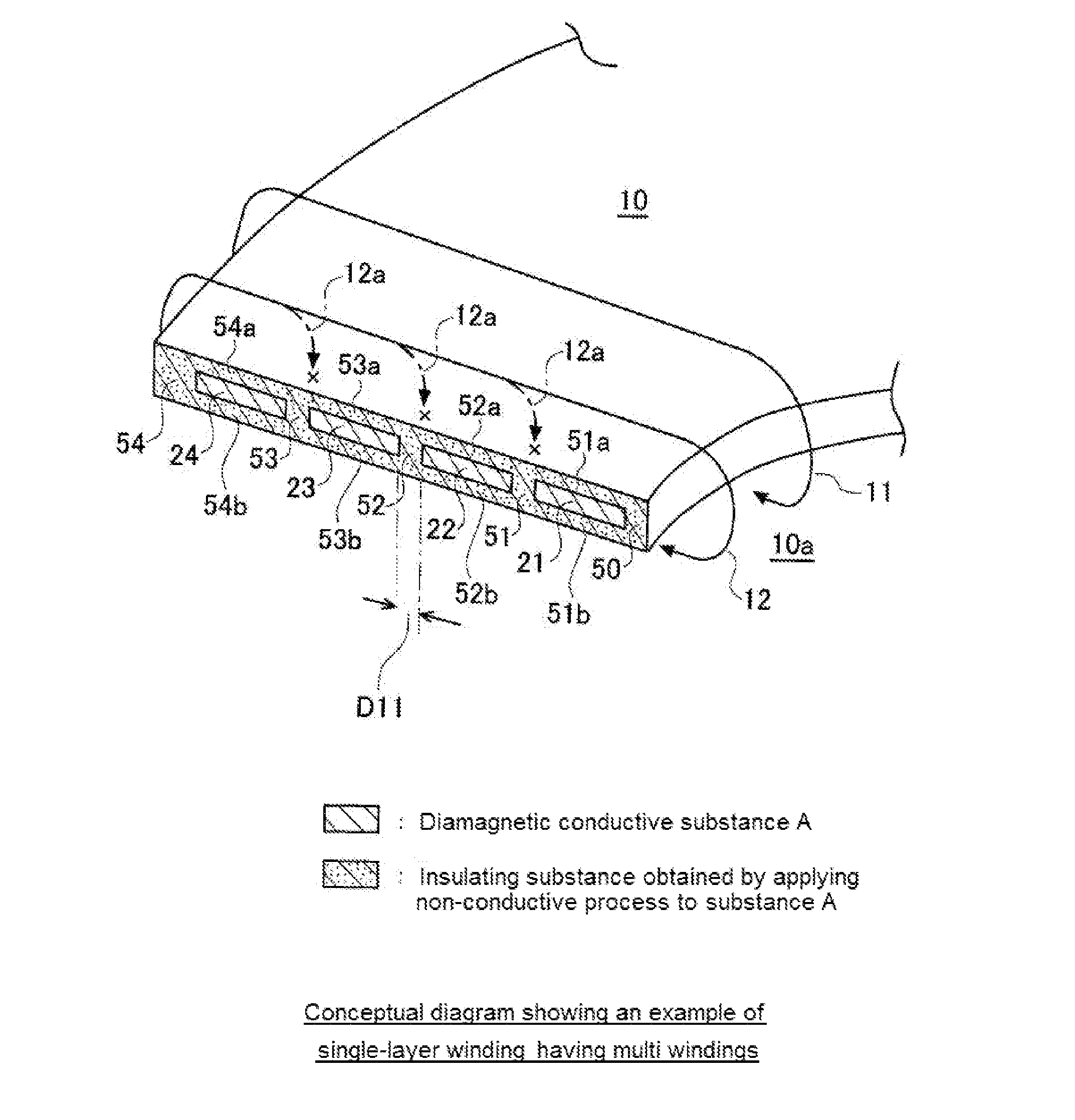
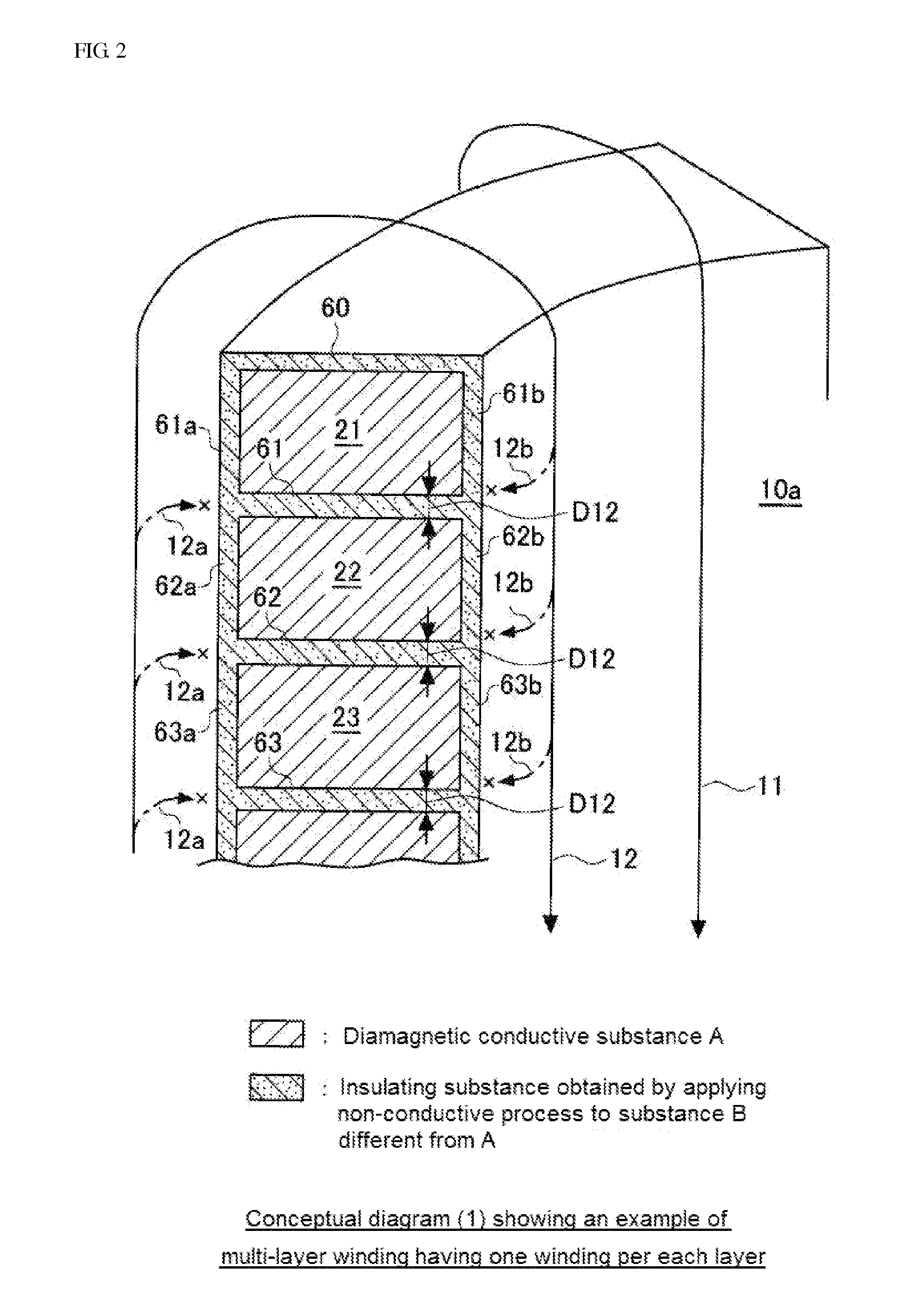
[0081]As described above, a wire wound device according to the present invention comprises a winding having a plurality of encircling conductor parts made of a conductive substance upon a predetermined winding pattern, and an insulation layer interposed between a pair of encircling conductor parts adjacent to each other among the plurality of encircling conductor parts forming the winding, the insulation layer comprising an insulating substance formed by performing a non-conductive process of a diamagnetic conductive substance.

[0082]In one embodiment of the wire wound device according to the present invention, the diamagnetic conductive substance before performing the non-conductive process, which is to be the insulation layer, and the conductive substance constituting ...


PUM


Abstract

Provided are a wire wound device that can minimize the flow of magnetic fluxes into gaps between the adjacent encircling conductor parts and achieve high efficiency, even if no magnetic core formed from a magnetic substance is inserted, and also a method for manufacturing the device, the wire wound device comprising: a winding having a plurality of encircling conductor parts made of a conductive substance upon a predetermined winding pattern; and an insulation layer interposed between a pair of encircling conductor parts adjacent to each other among the plurality of encircling conductor parts constituting the winding, the insulation layer comprising an insulating substance formed by performing a non-conductive process of a diamagnetic conductive substance.

Description


Claims


Application Information

Patent Timeline
Owner MORI RYUTARO
Why Eureka
Try Eureka