System for Cooling a Hyperbaric Chamber

a cooling system and hyperbaric chamber technology, applied in the direction of liquid fuel engines, heating types, lighting and heating apparatus, etc., can solve the problems of high maintenance cost, hot and uncomfortable environment, and methods with drawbacks

Active Publication Date: 2013-12-26
MCKEEMAN BRUCE ELGIN
View PDF10 Cites 3 Cited by
  • Summary
  • Abstract
  • Description
  • Claims
  • Application Information

AI Technical Summary

Problems solved by technology

As a result, hyperbaric chambers without a cooling system result in a very hot and uncomfortable environment.
However, these methods have drawbacks.
Chillers have issues with condensation and mold, and also tend to be high maintenance.
Chlorofluorocar

Method used


Image

  • System for Cooling a Hyperbaric Chamber
  • System for Cooling a Hyperbaric Chamber
  • System for Cooling a Hyperbaric Chamber

Examples


Embodiment Construction

[0016]All illustrations of the drawings are for the purpose of describing selected versions of the present invention and are not intended to limit the scope of the present invention.

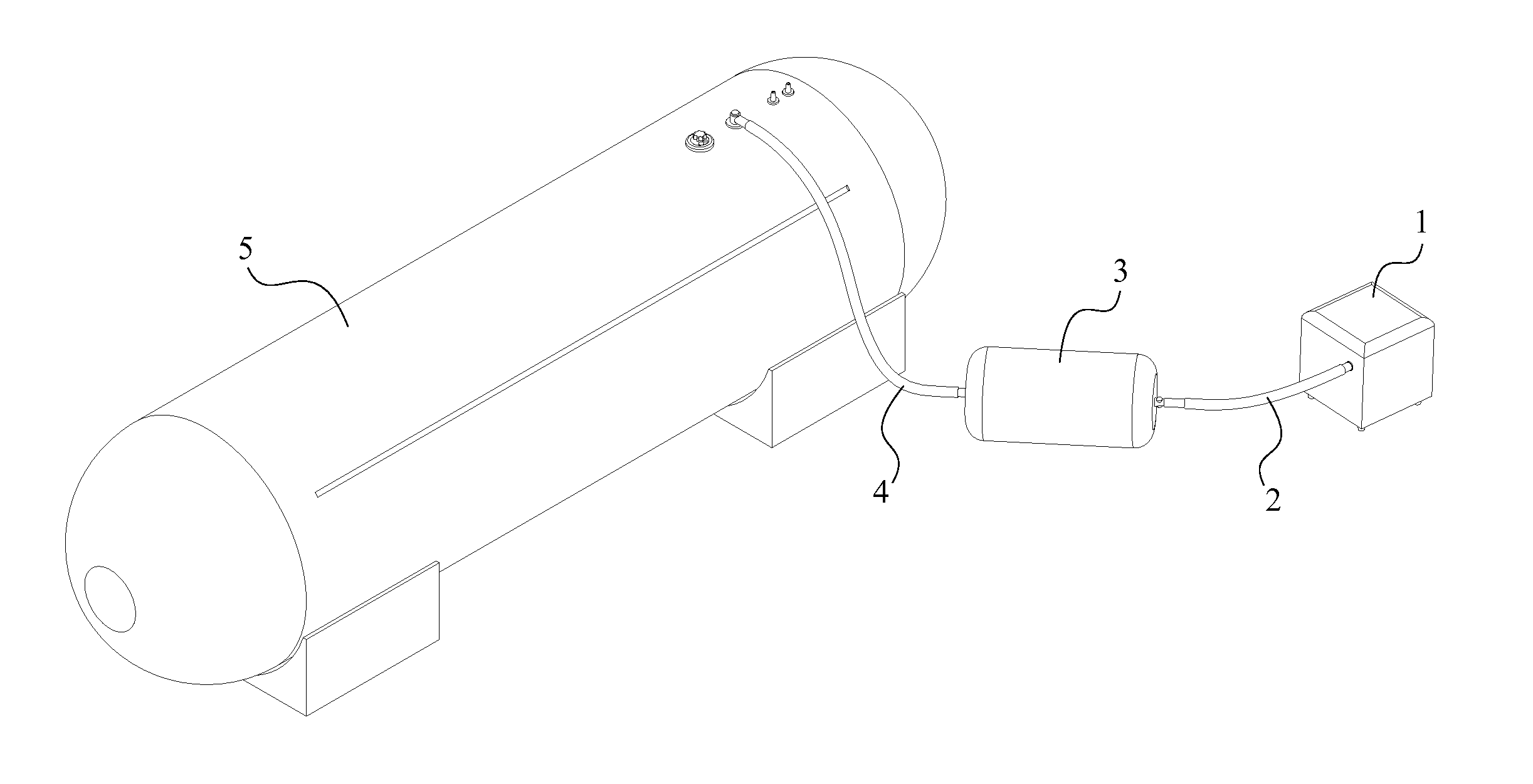
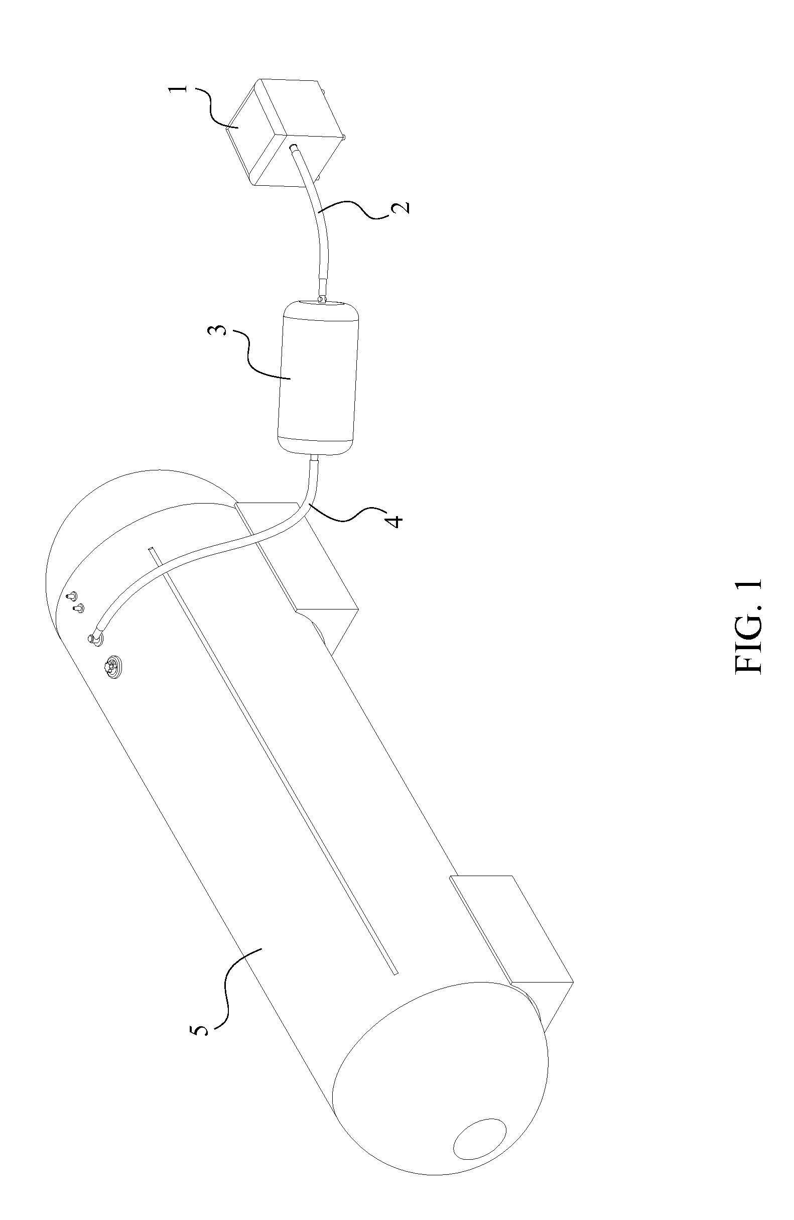
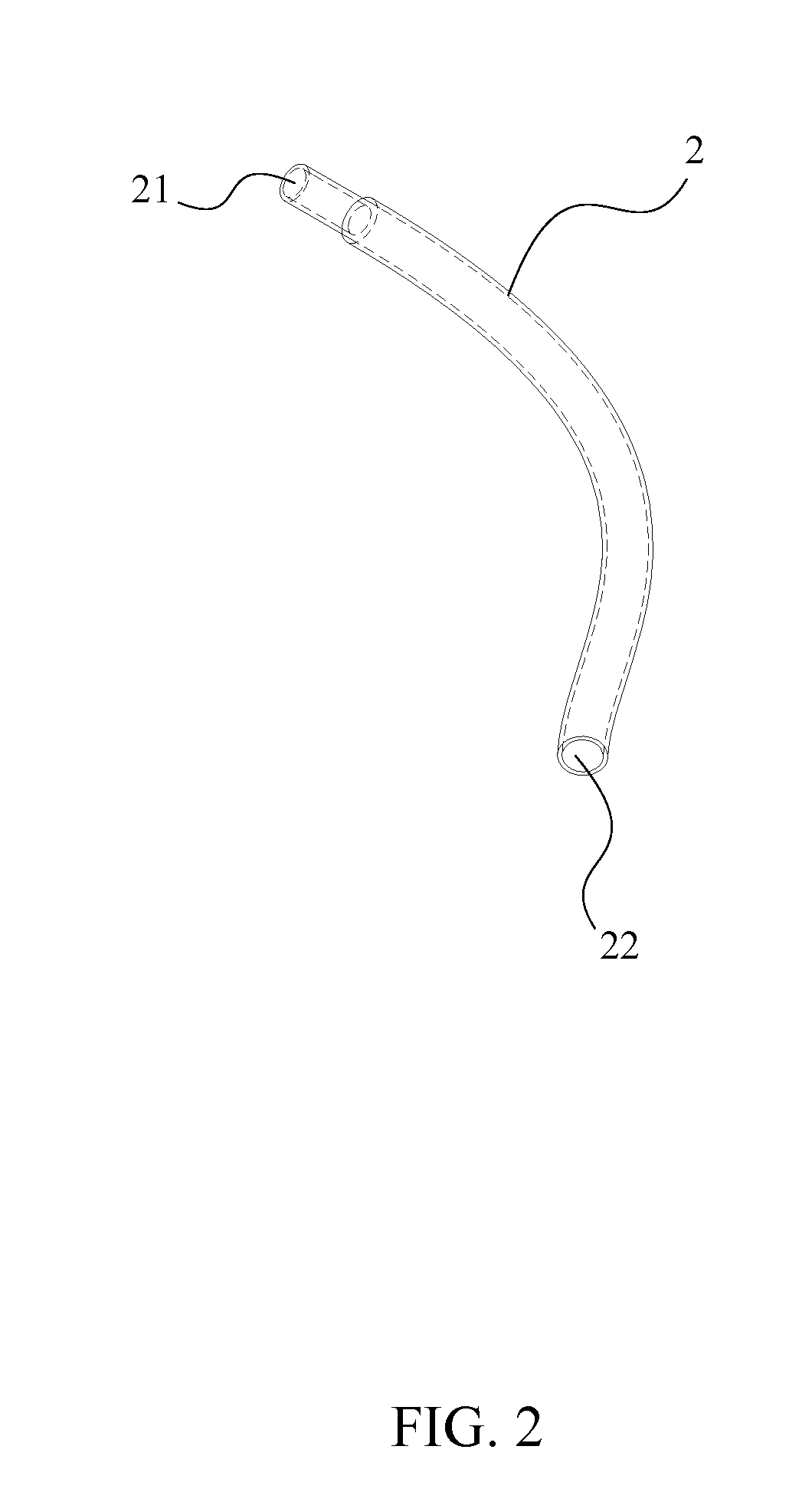
[0017]The present invention is a system for cooling a hyperbaric chamber which comprises a compressor 1, a first hose 2, a cooling unit 3, a second hose 4, and a hyperbaric chamber 5. In reference to FIG. 1, the compressor 1 is fluidly connected with the cooling unit 3 by the first hose 2, and the cooling unit 3 is fluidly connected with the hyperbaric chamber 5 by the second hose 4.

[0018]The compressor 1 used within the present invention can be any type of air compressor 1 which is able to compress or pressurize air so that the cooling unit 3 and the hyperbaric chamber 5 can be pressurized according to system requirements. Since the compression of the air generates heat; compressed air from the compressor 1 outputs warm air compare to the ambient temperature. The compressor 1 comprises a male compressed...


PUM


Abstract

A system for cooling a hyperbaric chamber includes a compressor, a first hose, a cooling unit, a second hose, and a hyperbaric chamber. The first hose fluidly connects the compressor to the cooling unit, and the second hose fluidly connects the cooling units to the hyperbaric chamber. Compressed air from the compressor travels through a first pressure relief fitting and a second pressure relief fitting, where the compressed air is depressurized according to the system requirements. During the depressurization, the compressed air cools down because of the depressurization and creates a comfortable environment within the hyperbaric chamber.

Description

[0001]The current application claims a priority to the U.S. Provisional Patent application Ser. No. 61 / 663,093 filed on Jun. 22, 2012.FIELD OF THE INVENTION[0002]The present invention relates generally to a system for cooling a hyperbaric chamber. More specifically, the present invention routes a compressor through a cooling system, reducing pressure and temperature in a connected hyperbaric chamber.BACKGROUND OF THE INVENTION[0003]Hyperbaric chambers are commonly used in the fields of diving and hyperbaric medicine. Hyperbaric chambers are pressurized vessels designed for human occupancy, and can be designed with either a soft or hard shelled construction. The act of pressurizing air generates heat in the enclosed environment of the hyperbaric chamber. As a result, hyperbaric chambers without a cooling system result in a very hot and uncomfortable environment.[0004]Because of the heat generated in a hyperbaric chamber, many existing hyperbaric chambers include some sort of cooling ...

Claims


Application Information

Patent Timeline
IPC IPC(8): F04D29/58
CPCF04D29/58A61G10/026F24F5/00A61G2210/70F24F5/0085
Inventor MCKEEMAN, BRUCE ELGIN
Owner MCKEEMAN BRUCE ELGIN
Why Eureka
Try Eureka