A wind farm reactive power control method and system

A technology for power control and wind farms, applied in control systems, reactive power adjustment/elimination/compensation, wind power generation, etc., can solve problems such as equipment waste, failure to take into account, and failure to meet the system, so as to improve safety and maintain The effect of stabilizing and suppressing voltage fluctuations

Active Publication Date: 2011-12-28
GUODIAN UNITED POWER TECH
View PDF5 Cites 55 Cited by
  • Summary
  • Abstract
  • Description
  • Claims
  • Application Information

AI Technical Summary

Problems solved by technology

GE's WindVAR system can ensure that the output reactive power of wind turbines can track the voltage changes at the access points in real time, but it uses wind turbines as the control unit and lacks unified planning for the reactive power of the entire wind farm. A large reactive power flow is formed among the units, and even the reactive power output capacity of some units reaches the limit, reducing the stability of the wind farm system.
[0006] The Chinese invention patent application with the application number 201010172546.7 "Coordinated Control Method for Wind Farm Reactive Voltage" discloses a wind farm reactive voltage control method. Give the calculation method of reactive power reference quantity
In addition, it does not take into account the centralized reactive power compensation equipment in the wind farm in the command distribution of reactive power. If only the generator sets output reactive power, it may not be able to meet the needs of the system and cause waste of equipment

Method used


Image

  • A wind farm reactive power control method and system
  • A wind farm reactive power control method and system
  • A wind farm reactive power control method and system

Examples


Embodiment Construction

[0027] The technical solutions of the present invention will be further described below in conjunction with the accompanying drawings and through specific implementation methods.

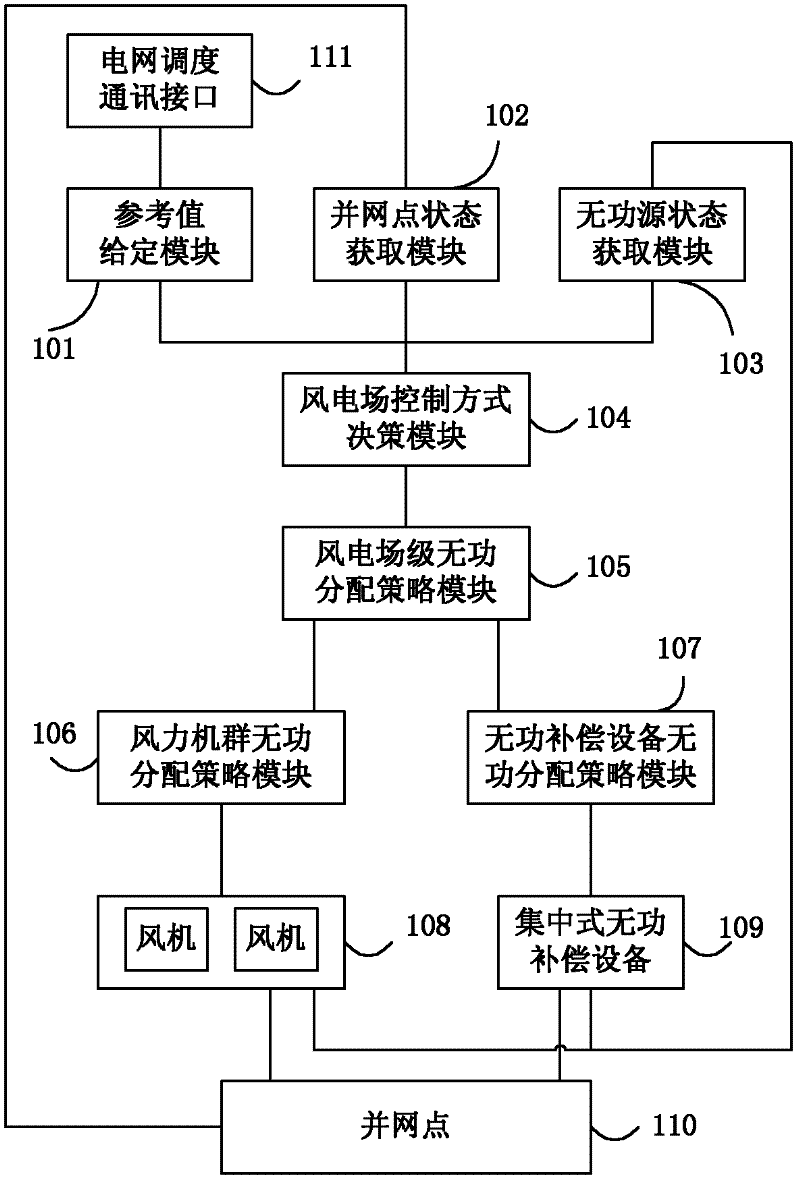
[0028] figure 1 It is a structural schematic diagram of a wind farm reactive power control system in a specific embodiment of the present invention. Such as figure 1 As shown, the wind farm reactive power control system includes a reference value setting module 101, a grid-connected point status acquisition module 102, a reactive power source status acquisition module 103, a wind farm control mode decision-making module 104, and a wind farm-level reactive power distribution strategy module 105 , wind power fleet reactive power distribution strategy module 106 , reactive power distribution strategy module 107 for reactive power compensation equipment, wind turbine 108 , centralized reactive power compensation device 109 and grid connection point 110 .

[0029] Among them, the reference value given mo...


PUM


Abstract

The invention discloses a wind power station reactive power control method and a system. The wind power station high voltage side bus voltage is used as a control target, the reactive power is used as the regulating quantity, the wind power station voltage control strategy and the power factor control strategy are selected or the system reactive power output is forcibly controlled to be a constant value according to the wind power station voltage fluctuation range and the power factors, and in addition, the reactive power output values of each fan and integrated reactive compensation equipment in the wind power station are determined according to the reactive power reference values required to be output by the wind power station. When the technology of the invention is adopted, the reactive power output of the wind power station networking points meets the system requirements for inhibiting the bus voltage fluctuation and regulating the wind power station power factor, and in addition, the reactive power output of each wind power generator set and integrated reactive compensation equipment in the wind power station can be controlled in a harmonious way.

Description

technical field [0001] The invention relates to the technical field of wind power generation, in particular to a method and system for controlling reactive power of a wind farm. Background technique [0002] Wind energy is random and uncontrollable, and the output power and voltage of wind turbines also fluctuate randomly, which is a source of interference to relatively stable power systems. The centralized grid connection of large-scale wind farms has brought a series of far-reaching impacts on the safe operation and economic dispatch of the power system. Among them, the voltage-reactive power problem caused by wind farms is the first to attract attention, and it is also one of the most common problems in actual operation. . [0003] Early wind farms controlled the reactive power of wind farms by switching capacitor banks. In the case of a weak grid structure, affected by random changes in wind energy, these capacitor banks alone cannot keep up with the impact of wind spe...

Claims


Application Information

Patent Timeline
Patent Type & Authority Applications(China)
IPC IPC(8): H02J3/46H02J3/18H02P9/00
CPCY02E10/763Y02E40/30Y02E10/76
Inventor 张宪平潘磊原美琳徐佳园秦明
Owner GUODIAN UNITED POWER TECH
Why Eureka
Try Eureka