Fuel cell power system having multiple fuel cell modules

a fuel cell power system and fuel cell technology, applied in the direction of cell components, final product manufacturing, sustainable manufacturing/processing, etc., can solve the problems of insufficient single fuel cell stack, inability to scale up or down, and difficulty in ensuring that the fuel cell stack will operate efficiently under all the possible operating conditions

Inactive Publication Date: 2005-05-26
HYDROGENICS CORP
View PDF3 Cites 54 Cited by
  • Summary
  • Abstract
  • Description
  • Claims
  • Application Information

AI Technical Summary

Benefits of technology

[0013] It is therefore an object of the invention to provide a fuel cell power system having multiple, modular fuel cell stacks thus providing flexible, robust and scaleable fuel cell solutions for a variety of applications.
[0014] In accordance with one aspect of the invention, a fuel cell power system includes a plurality of fuel cell power modules, each fuel cell power module including a fuel cell for generating electrical power; a plurality of local controllers, each local controller controlling one respective fuel cell power module; and a master controller for controlling the local controllers. By including both local and master controllers, this system provides a two-tier control architecture that is highly flexible, scaleable and robust. Additional fuel cell power modules can thus be added or removed in a modular fashion to accommodate varying power requirements.

Problems solved by technology

All of these requirements are exceedingly demanding and make it difficult to ensure that a fuel cell stack will operate efficiently under all the possible ranges of operating conditions.
In some applications, where a large power output is required, a single fuel cell stack may not be sufficient.
Although this design offers a simple way to meet the power requirement while minimizing the size of the fuel cell power module, it suffers from a number of problems.
First, the power module has to be custom-made and cannot be scaled up or down.
Moreover, the fuel cell power module lacks flexibility.
Any malfunctioning component tends to deleteriously affect the performance of the overall system and often leads to complete system shutdown.

Method used


Image

  • Fuel cell power system having multiple fuel cell modules
  • Fuel cell power system having multiple fuel cell modules
  • Fuel cell power system having multiple fuel cell modules

Examples


first embodiment

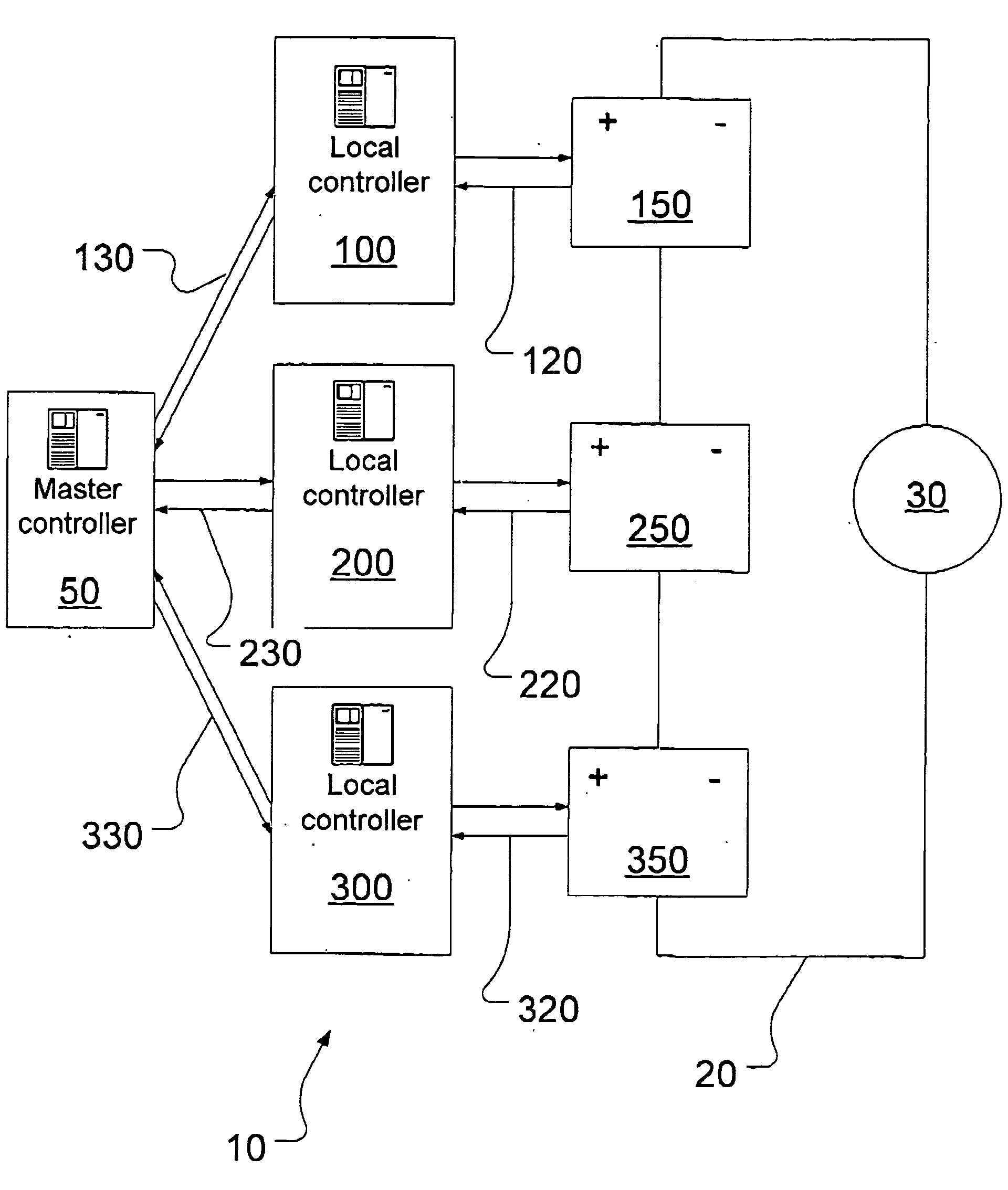
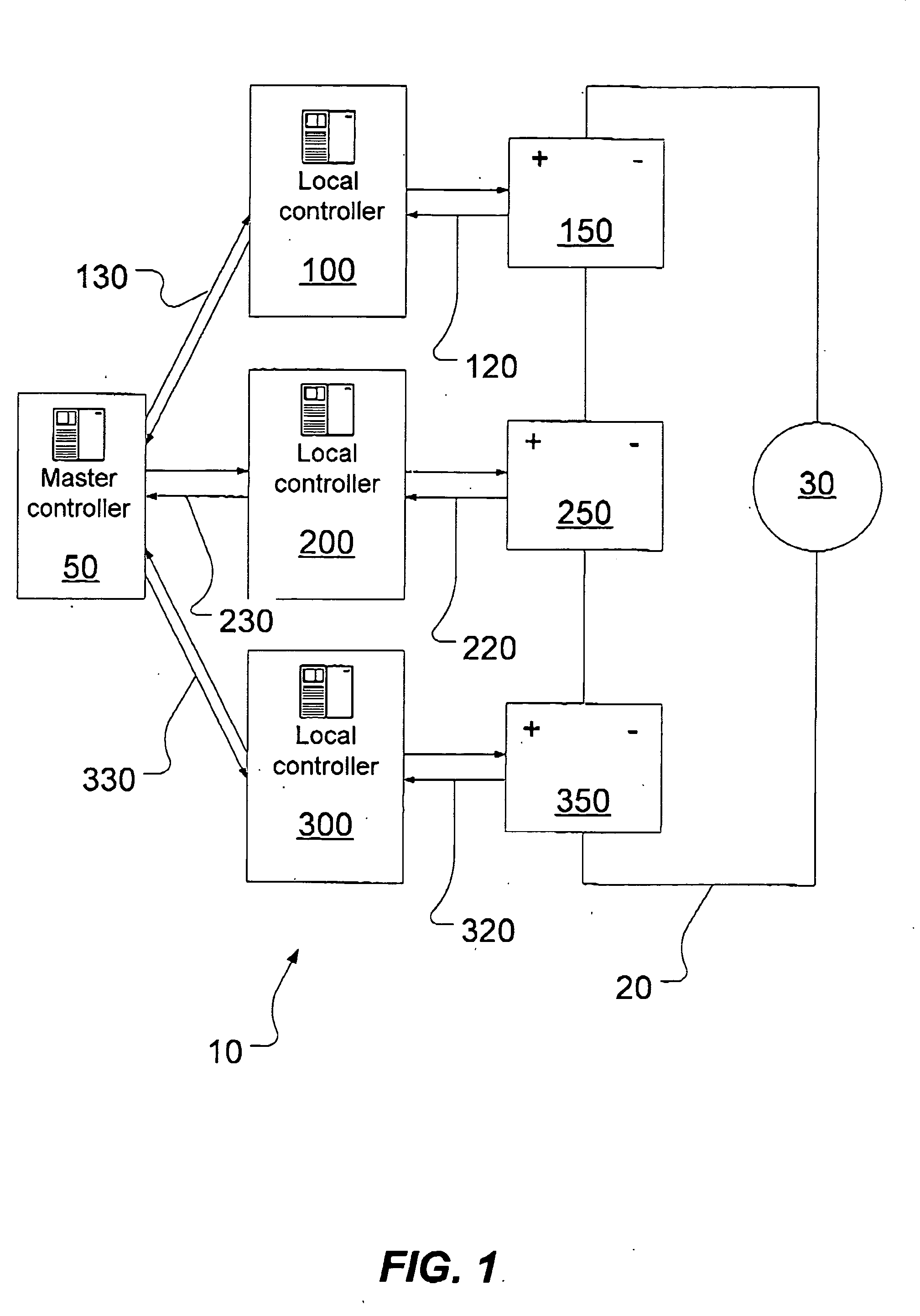
[0023]FIG. 1 shows a schematic of a fuel cell power system, generally designated by reference numeral 10, in accordance with the present invention.

[0024] The fuel cell power system 10 includes multiple fuel cell power modules each having a fuel cell and associated peripheral devices for supplying reactants to the fuel cell and for collecting current and reaction byproducts from the fuel cell. FIG. 1 shows a fuel cell power system having three such power modules 150, 250, 350 although it is to be expressly understood that the term “multiple” (or “a plurality of”) should be construed as meaning more than one. In other words, the fuel cell power system 10 according to the present invention has at least two fuel cell power modules. For example, a fuel cell power system used to power a vehicle such as a car (typically requiring about 80-100 kW of power) could use 4 or 5 modules each having a power output of 20 kw. Alternatively, a smaller (or larger) number of modules each having a highe...

second embodiment

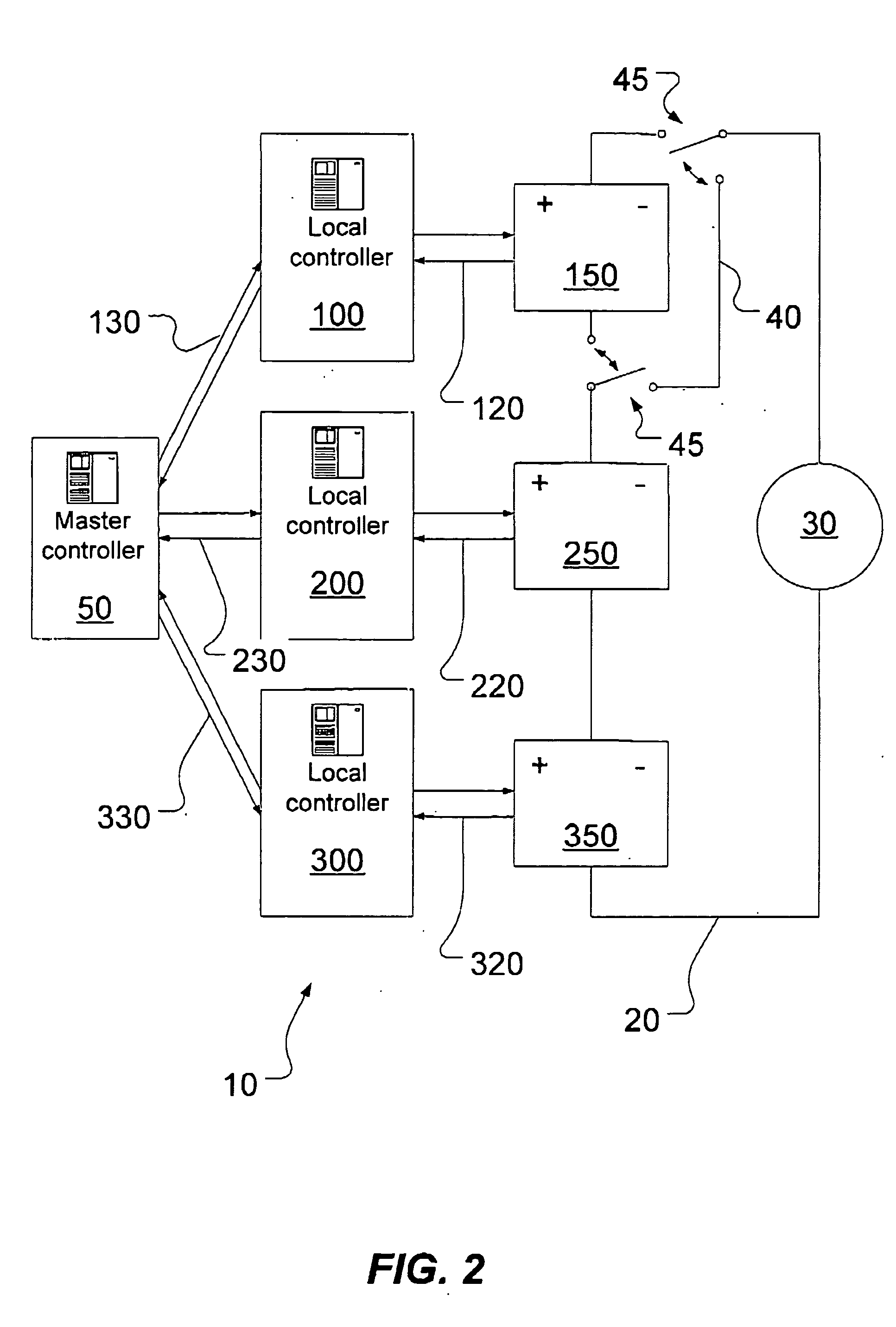
[0037] As shown in FIG. 2, a fuel cell power system 10 in accordance with the present invention includes a bypass 40 (possibly also known as a bypass line or a bypass circuit). The bypass 40 enables the first fuel cell power module 150 to be bypassed in the event that it malfunctions, fails or is no longer required due to a diminished overall power requirement. The bypass 40 is controlled by the master controller 50 which operates a pair of switches 45 which can be opened to electrically isolate the fuel cell power module 150. Although FIG. 2 only shows a single bypass 40, it should be understood that the fuel cell power system 10 could include a bypass for each fuel cell power module so that any given module can be shut down and bypassed. Control of the bypass 40 can be managed by the master controller 50 based on overall system power requirements and performance or fault data from the local controller. In a variant, the local controller may also retain a certain autonomy to initia...


PUM

PropertyMeasurementUnit
poweraaaaaaaaaa
poweraaaaaaaaaa
areaaaaaaaaaaa

Abstract

A fuel cell power system has a plurality of fuel cell power modules, each module including a fuel cell and associated peripheral devices. Each fuel cell power module is controlled by its own local controller. A master controller controls each of the local controllers in accordance with overall system requirements. Optionally, a bypass allows the master controller to shut down and bypass a particular fuel cell power module, providing this system with greater flexibility, robustness and reliability. The modular system architecture also simplifies manufacturing, maintenance and repair.

Description

CROSS-REFERENCE TO RELATED APPLICATIONS [0001] This application claims priority from U.S. Provisional Patent Application Ser. No. 60 / 513,221 filed Oct. 23, 2003.FIELD OF THE INVENTION [0002] The present invention relates generally to a fuel cell power system and, more particularly, to a method of operating a fuel cell power system having multiple fuel cell modules. BACKGROUND OF THE INVENTION [0003] A fuel cell is an electrochemical device that produces an electromotive force by bringing the fuel (typically hydrogen) and an oxidant (typically air) into contact with two suitable electrodes and an electrolyte. A fuel, such as hydrogen gas, for example, is introduced at a first electrode where it reacts electrochemically in the presence of the electrolyte to produce electrons and cations in the first electrode. The electrons are circulated from the first electrode to a second electrode through an electrical circuit connected between the electrodes. Cations pass through the electrolyte ...

Claims


Application Information

Patent Timeline
Patent Type & Authority Applications(United States)
IPC IPC(8): B60L11/18H01M8/04H01M8/24
CPCB60L11/1881B60L11/1892H01M8/04679H01M8/0494H01M8/04992Y02T90/32H01M8/2495H01M2250/20Y02T90/34Y02E60/50H01M8/249B60L58/30B60L58/33Y02P70/50Y02T90/40
Inventor FREEMAN, NORMAN A.BURANY, STEPHEN
Owner HYDROGENICS CORP
Why Eureka
Try Eureka