
Spiral screw fluid turbine having axial void

a technology of fluid turbine and screw, which is applied in the direction of liquid fuel engine, vessel construction, marine propulsion, etc., can solve the problems of increasing the cost of installation, causing significant problems for energy generating turbines, and increasing the cost of turbines

Inactive Publication Date: 2013-12-26
RAJAKARUNA UPPALA
View PDF5 Cites 25 Cited by
  • Summary
  • Abstract
  • Description
  • Claims
  • Application Information

AI Technical Summary

Benefits of technology

This patent is about an improved type of turbine. The improvements will be clear from the text description and drawings. The technical effects of the improvements will be known from the patent.

Problems solved by technology

It is now known that energy generating turbines can create significant issues for marine life, which can be harmed by the rotating turbine blades.
So far, the various known proposals to reduce the potential harm to marine life only serve to add to the expense of the turbine and the expense of the installation.

Method used


Image

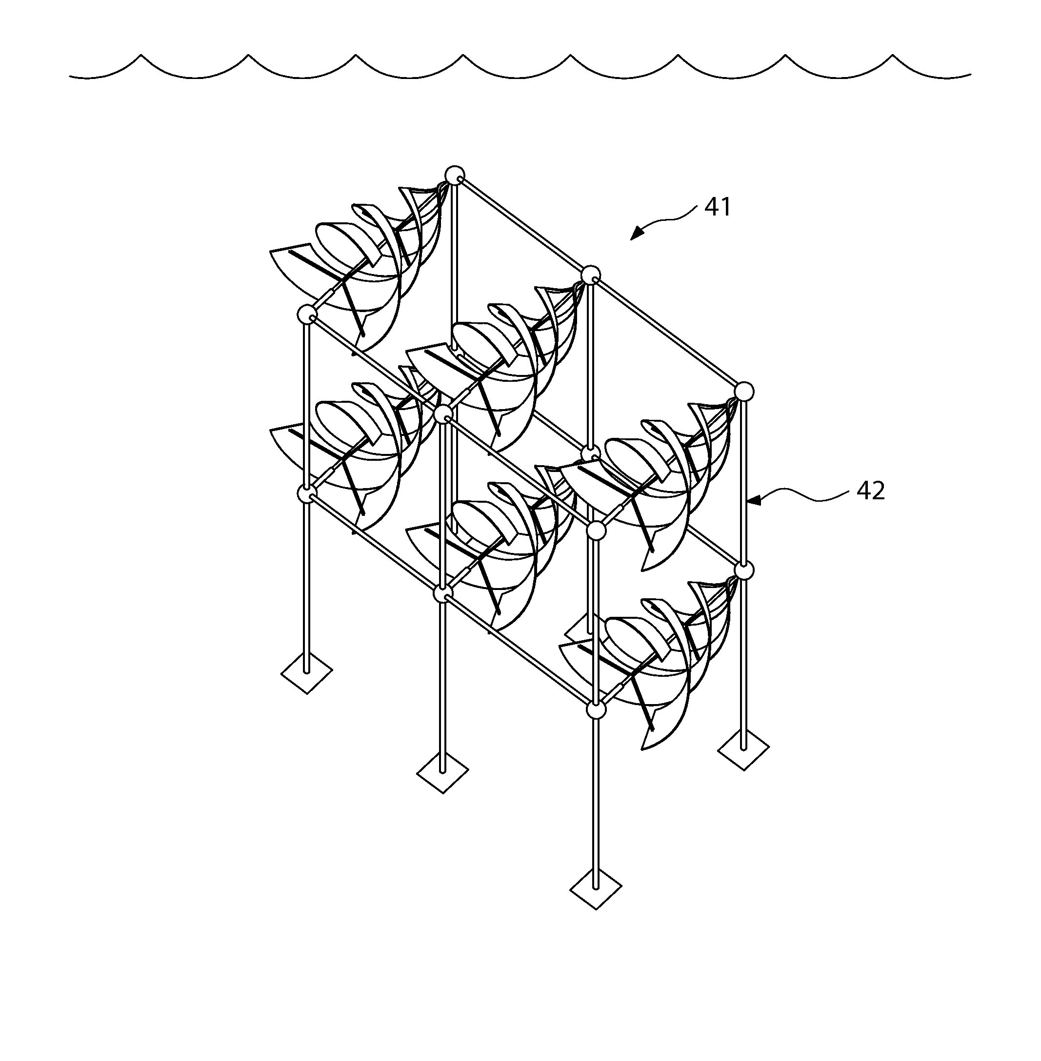
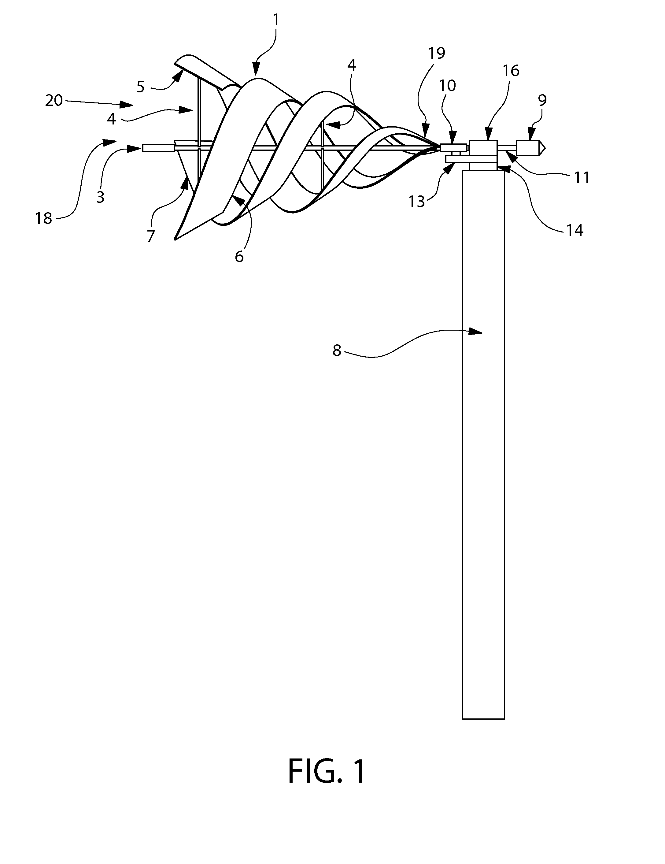
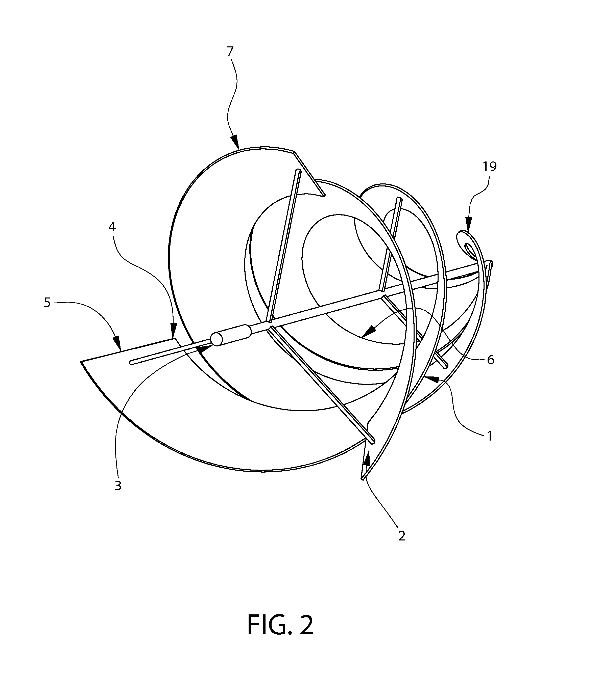
  • Spiral screw fluid turbine having axial void
  • Spiral screw fluid turbine having axial void
  • Spiral screw fluid turbine having axial void

Examples


Embodiment Construction

[0025]The description of illustrative embodiments according to principles of the present invention is intended to be read in connection with the accompanying drawings, which are to be considered part of the entire written description. In the description of embodiments of the invention disclosed herein, any reference to direction or orientation is merely intended for convenience of description and is not intended in any way to limit the scope of the present invention. Relative terms such as “lower,”“upper,”“horizontal,”“vertical,”“above,”“below,”“up,”“down,”“left,”“right,”“top” and “bottom” as well as derivatives thereof (e.g., “horizontally,”“downwardly,”“upwardly,” etc.) should be construed to refer to the orientation as then described or as shown in the drawing under discussion. These relative terms are for convenience of description only and do not require that the apparatus be constructed or operated in a particular orientation unless explicitly indicated as such. Terms such as ...


PUM


Abstract

A spiral turbine includes an axle configured to rotate and one or more spiral blades coupled to the axle by one or more support connections. Each spiral blade is formed around and outside of a conical inner space which is coaxial with the axle.

Description

CROSS REFERENCE TO RELATED APPLICATIONS[0001]Priority is claimed to U.S. provisional patent application No. 61 / 656,851, filed Jun. 7,2012, the disclosure of which is incorporated herein by reference in its entirety.FIELD OF THE INVENTION[0002]The field of the present invention relates to turbine blades, and more specifically to turbine blades for generation of electric energy.BACKGROUND OF THE INVENTION[0003]Turbine blades are generally designed to capture energy from flowing fluids, such as flowing water or air. Various designs of wind mills and water turbines exist today and are used in many regions around the world for producing electric power through rotation powered by the flow of fluids, most commonly air or water.[0004]Many proposals have been made for gathering electricity from tidal and other water flows, using hydrokinetic energy generation. Initial proposals for hydrokinetic energy genera (ion use turbine blades that are able to rotate under pressure from the flow of wate...

Claims


Application Information

Patent Timeline
IPC IPC(8): F01D5/02
CPCF01D5/023F03B17/061F03D1/0608F05B2250/232F05B2250/15Y02E10/20Y02E10/72F05B2210/16F05B2240/40Y02E10/30
Inventor RAJAKARUNA, UPPALAGEEKIYANAGE, BUSHITHA SEHAN
Owner RAJAKARUNA UPPALA
Learn More