Floating screw turbines device

a screw turbine and screw technology, applied in the direction of engine fuction, engine working fluid, sea energy generation, etc., can solve the problems of less effective energy extraction of waterwheel, less effective waterwheel, and inability to adjust waterwheel, so as to achieve the effect of maximizing the fluid velocity

Active Publication Date: 2019-10-10
UPRAVLJANJE KAOTICNIM SUSTAVIMA D O O
View PDF0 Cites 2 Cited by
  • Summary
  • Abstract
  • Description
  • Claims
  • Application Information

AI Technical Summary

Benefits of technology

[0025]In another embodiment, deflectors / diffusors are held in the desired position relative to the water duct by locking the pitch of the hinges by a set of wedges.
[0026]In yet another embodiment, deflectors / diffusors are continuously adjustable in time to the desired position relative to the water ducts by using hydraulic or electromechanical actuators. In one variant, the deflectors / diffusors are continuously adjustable in accordance with the inlet water flow velocity where the deflectors' / diffusors' pitch is selected according to previously performed computational fluid dynamics simulation for the turbine device in order to maximize fluid velocity across the water ducts. In another variant a proportional-integral-derivative controller is used for the same purpose. The water flow velocity can be measured in one or more points used contact or non-contact velocity measuring systems, such as Doppler radar devices mounted on the deck frame.
[0027]Two or more floating screw turbines devices with adjustable rear deflectors / diffusors can be used in a parallel, serial or mixed configuration for converting the fluid flow into rotational mechanical power.

Problems solved by technology

Hydrofoils, as far as can be deducted, are not adjustable.
Also, a waterwheel seems to be less effective for efficient power extraction.
Also, a waterwheel seems to be less effective for energy extraction, similar as above cited prior art.

Method used


Image

  • Floating screw turbines device
  • Floating screw turbines device
  • Floating screw turbines device

Examples


Embodiment Construction

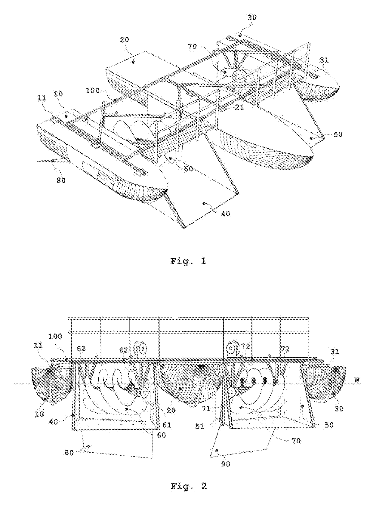
[0037]An aspect of the present invention relates to the floating screw turbines device with adjustable rear deflectors / diffusors where a liquid flow, i.e. its kinetic energy, is converted to turbines rotary motion. In this detailed description, only one embodiment will be discussed in detail, with possible variants. The average person skilled in the art will simply deduce trivial variants of an aspect of the invention. As mentioned earlier, the term—screw turbine—as used herein refer to any helical turbine used in the prior art. A particularly good review, with examples, is given in the previously cited document WO2012 / 019307A1.

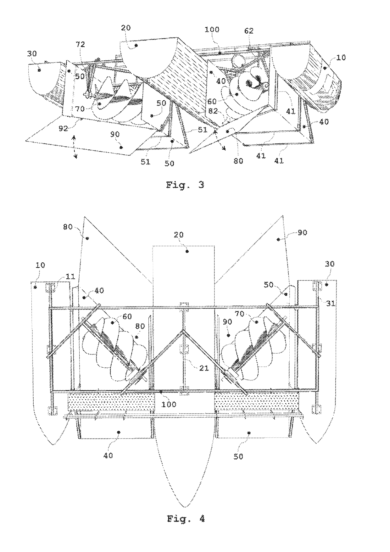
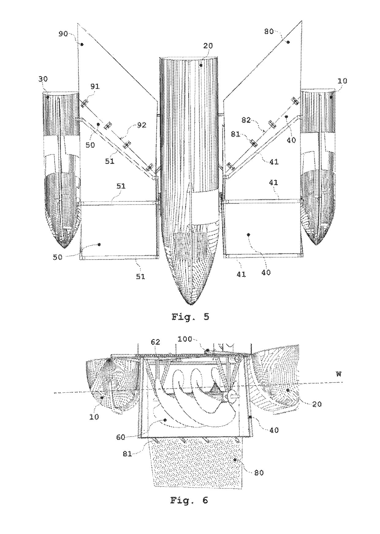
[0038]A floating screw turbines device, as depicted in FIG. 1, consists of three pontoons (10, 20, 30) spaced apart and fixed to the deck frame (100). The pontoons (10, 20, 30) can be formed in any manner known in the art, its technical role is to provide buoyancy and stability to the structure. The pontoons (10, 20, 30) can be manufactured as hollow metal or...


PUM


Abstract

A floating screw turbine device with adjustable rear deflectors/diffusors is disclosed. Three pontoons, spaced apart, carry water ducts in which screw turbines are mounted. Screw turbines, mounted in a V configuration, have mirror symmetrical pitches of the screws measured over the centre of symmetry that passes through the central pontoon. Such a configuration minimizes the vibration of the device. Rear deflectors/diffusors have an adjustable pitch relative to the floors of the water ducts by which they can affect the water flow velocity through the water ducts. In one embodiment, the optimum pitch is selected according to the previously performed computational fluid dynamics simulation for the device, where the pitch is changed using hydraulic or electromechanical actuators. In another variant an artificial neural network is taught to model a global function of the system dynamics in order to achieve optimal operation.

Description

CROSS REFERENCE TO RELATED APPLICATIONS[0001]This application is the U.S. National Phase Application of PCT / EP2016 / 076002, filed Oct. 27, 2016, the contents of such application being incorporated by reference herein.TECHNICAL FIELD[0002]Present invention relates to a floating screw turbines device with adjustable rear deflectors / diffusors where a liquid flow, i.e. its kinetic energy, is converted by means of turbines to rotary motion. The invention uses paired screw turbines with their rotation axis inclined to the direction of fluid flow. The invention is focused on components used for improvement of the turbine's technical characteristics, more particularly, on use of rear deflectors / diffusors on previously known turbine devices for maximisation of the extracted energy from a water flow.Technical Problem[0003]The essential technical problem which is solved by an aspect of the invention is an improvement in technical characteristics of floating screw turbine devices with respect to...

Claims


Application Information

Patent Timeline
Patent Type & Authority Applications(United States)
IPC IPC(8): F03B11/02F03B3/04F03B3/12
CPCF05B2260/80F05B2220/32F03B11/02F05B2210/11F05B2240/14F03B3/04F03B3/121F03B13/264F03B17/061F05B2240/12F05B2240/13F05B2240/243F05B2240/932F05B2250/25Y02E10/30Y02E10/20
Inventor KONCAR, NENADSOKOLIC, SANJINMUSTRA, JUREVUKMAN, DENISMACUT, ZORANMILAT, JOZO
Owner UPRAVLJANJE KAOTICNIM SUSTAVIMA D O O
Why Eureka
Try Eureka