
Grinding wheel

a technology of grinding disks and grinding wheels, which is applied in the direction of supporting wheels, grinding/polishing hand tools, metal-working equipment, etc., can solve the problems of short service life, disks must be changed, and high labor intensity

Inactive Publication Date: 2013-12-26
ROBERT BOSCH GMBH
View PDF10 Cites 4 Cited by
  • Summary
  • Abstract
  • Description
  • Claims
  • Application Information

AI Technical Summary

Benefits of technology

The invention is a grinding disk with a center point and a multiplicity of extraction holes. The extraction holes have a center point that lies on a single-hole radial line. The arrangement of the extraction holes is characterized by the properties that the center point of each extraction hole is on a single-hole circular with the grinding disk, and that the center point of all the extraction holes on a single-hole radial line is located on a common single-hole circle with the grinding disk. These properties ensure a good compromise between extraction capacity and uniformity, independence from the pattern of holes of the grinding pad and the positioning and stability of the grinding disk. The arrangement of the extraction holes on a single-hole radial line and on a single-hole circle ensures a relatively uniform arrangement of the extraction holes without the need for them to lie too close together to reduce stability. The number of circles of which the radius is smaller than the radius of the single-hole circle lies in the range from 2 to 5. The grinding disk has at most 5, preferably at most 4, more preferably at most 3, particularly preferably precisely 3, different radial line types. The center point of at least 3 extraction holes is arranged on each radial line type. The arrangement of the extraction holes on a single-hole radial line and on a single-hole circle ensures a good compromise between extraction capacity and uniformity. The number of extraction holes on a single-hole radial line and on a single-hole circle should be in the range from 20 to 100, preferably from 30 to 80.

Problems solved by technology

Machining a workpiece with a rotating grinding disk generates grinding dust, which without further measures would clog the grinding disk and therefore lead to short service lives.
The grinding disk must therefore be changed frequently, which is extremely laborious and uneconomical.
Finally, the distance between the holes should also on the one hand not be chosen to be too great, since otherwise uniform extraction is not possible.
On the other hand, however, the distance between the extraction holes must also not be too small, since the grinding disk could otherwise lose its stability and, for example, could break or tear at the areas between the extraction holes.

Method used


Image

  • Grinding wheel
  • Grinding wheel
  • Grinding wheel

Examples


Embodiment Construction

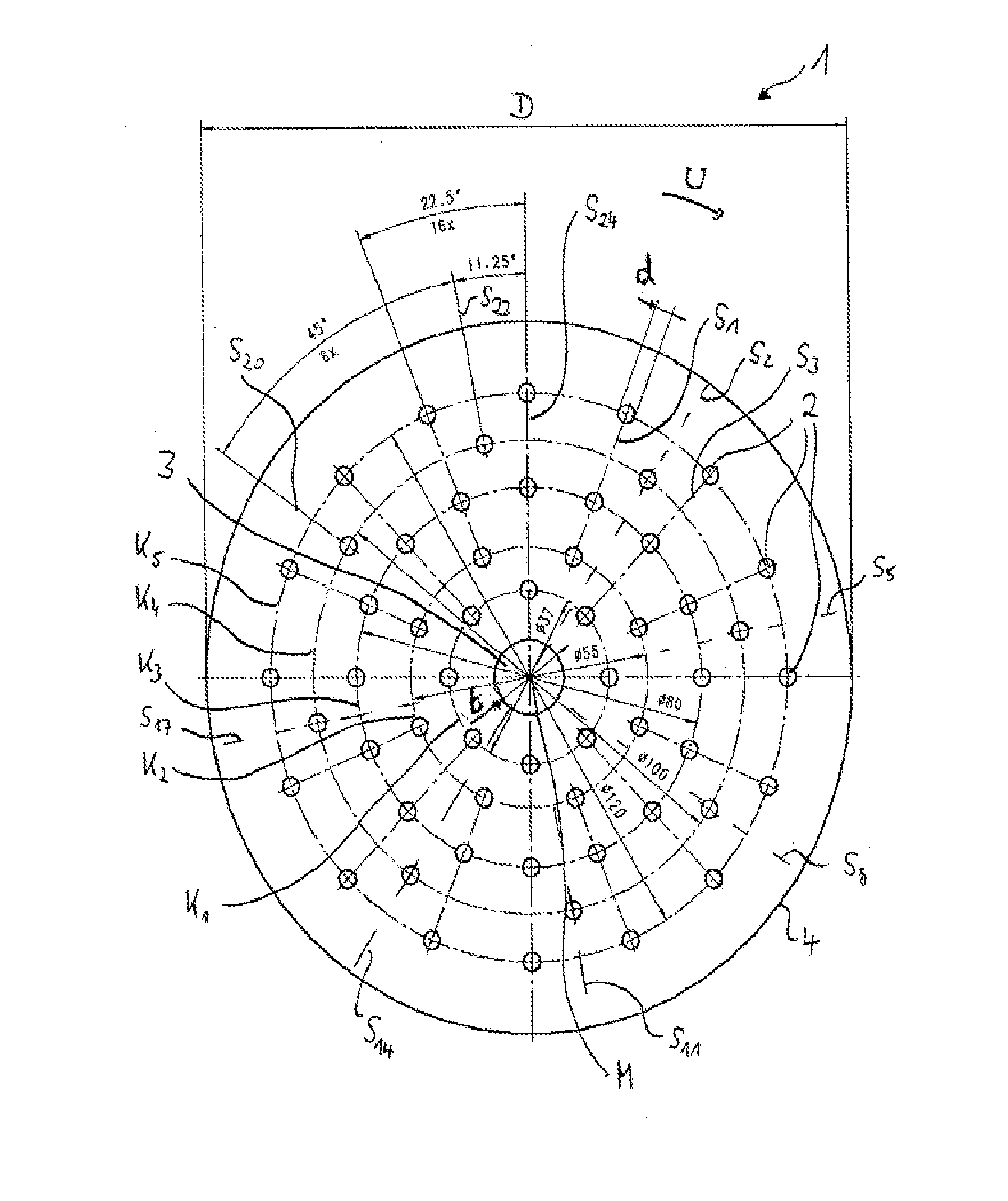
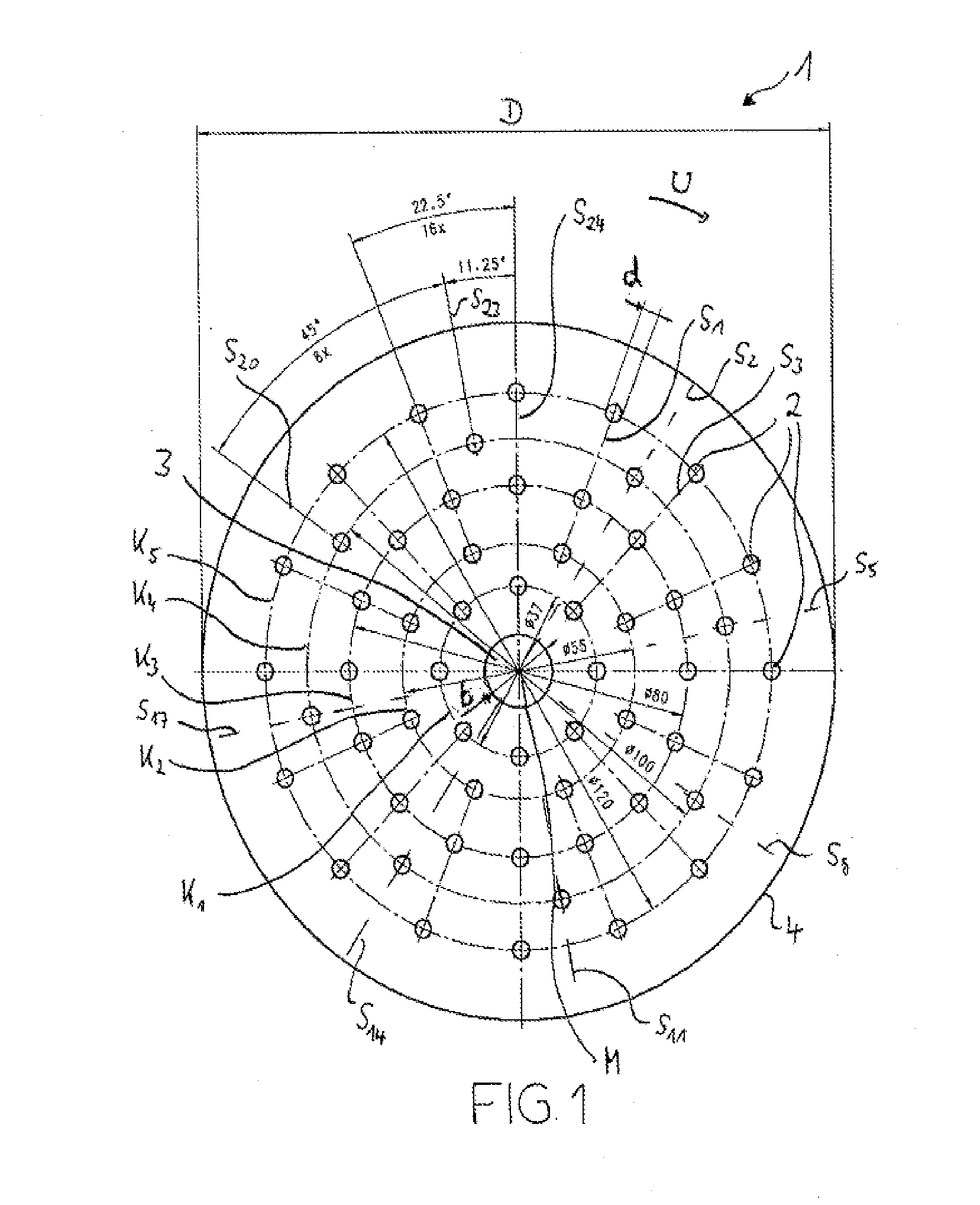
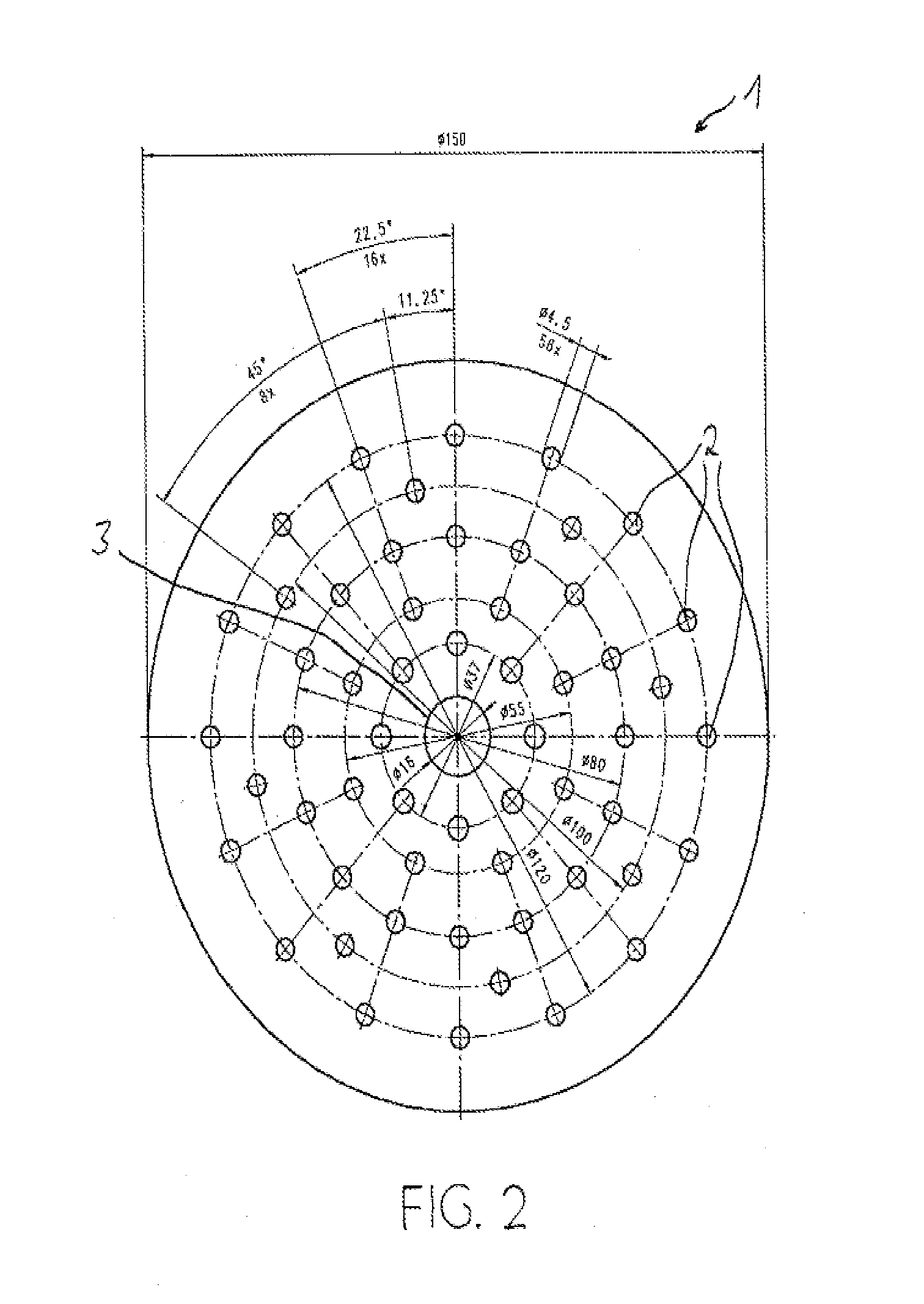
[0042]The first embodiment, represented in FIG. 1, shows a circular grinding disk 1 with a diameter D=150 mm. Arranged at the center of the grinding disk 1 is a circular fastening opening 3 with a diameter of b=16 mm, by means of which the grinding disk 1 can be connected in a way known per se to a grinding pad that is not represented here. The grinding disk 1 contains an imaginary center point M, which represents the geometrical center point of the circular outer circumference 4 of the grinding disk 1.

[0043]The grinding disk 1 contains a total of nL=56 circular extraction holes 2 with a diameter of 4 mm. The center point of each extraction hole 2 is arranged both on one of nS=24 radial lines extending from the center point M and on one of nK=5 circles of holes K1, . . . , K5 with associated radii r1=18.5 mm, r2=27.5 mm, r3=40 mm, r4=50 mm and r5=60 mm. Arranged on the circles of holes K1, . . . , K5 are the center points of nL1=8, nL2=8, nL3=16, nL4=8 and nL5=16 extraction holes 2,...


PUM


Abstract

A circular grinding wheel has a center point and defines a multiplicity of extraction holes, which, in particular, are circular extraction holes. The center point of each extraction hole is arranged at the point of intersection of a radial line extending from the center point of the grinding wheel with a circle of holes that is arranged concentrically with respect to the center point and that has a radius. At least one of the radial lines is a single-hole radial line, on which the center point of only a single extraction hole is arranged. The center points of all the extraction holes that are arranged on a single-hole radial line lie substantially on a common single-hole circle having a radius. Each radial line comprises the center point of an extraction hole on at least one radius on which the two radial lines that are adjacent to this radial line in the circumferential direction have no center point of an extraction hole.

Description

PRIOR ART[0001]The present invention relates to a circular grinding disk comprising a multiplicity of extraction holes according to the preamble of claim 1. Such grinding disks are also known as “multihole grinding disks”.[0002]Machining a workpiece with a rotating grinding disk generates grinding dust, which without further measures would clog the grinding disk and therefore lead to short service lives. The grinding disk must therefore be changed frequently, which is extremely laborious and uneconomical.[0003]To overcome this problem, grinding disks with extraction holes that pass through the grinding surface have long been known. The grinding dust can be discharged through these extraction holes. These grinding disks may be fastened to grinding pads, which likewise have corresponding extraction holes. This discharge is particularly effective if the grinding dust is actively extracted by producing a negative pressure in the grinding pad.[0004]Such grinding disks of the generic type...

Claims


Application Information

Patent Timeline
Patent Type & Authority Applications(United States)
IPC IPC(8): B24B55/06
CPCB24B55/06B24B55/102B24D9/08
Inventor ZAECH, ROMANEGGENBERGER, PETER
Owner ROBERT BOSCH GMBH
Learn More