Process for the treatment of gas phase alkaline chloride in a combustion plant, combustion plant for carrying out the process, and the use of a phosphorous substance for the treatment of alkaline chloride in gaseous phase in a combustion plant

Inactive Publication Date: 2009-10-15
VATTENFALL
View PDF5 Cites 0 Cited by
  • Summary
  • Abstract
  • Description
  • Claims
  • Application Information

AI Technical Summary

Benefits of technology

[0017]The technical advantage of the invention is thus that corrosive alkaline chloride is converted into a more stable composition by phosphatising, than is the case upon conversion into a sulphate.

Problems solved by technology

It is a known problem within the circle of persons skilled in the art, that chlorine which is formed in combustion of chlorine-containing fuel leads to corrosion in combustion plants.
Reactions between the alkaline chloride and iron oxide, e.g., which may take place on the said surfaces, results in formation of free chlorine which is strongly corrosive in this state.
The increase of the sulphur dioxide content in the flue-gas entails negative consequences in the form of increased SO2 emissions from the plant (problems with emission regulations and environmental permits) and an increased risk of low-temperature corrosion.
A non-solved problem is however that in some operational conditions the resulting sulphate is instable which may lead to a decreased technical effect.

Method used


Image

  • Process for the treatment of gas phase alkaline chloride in a combustion plant, combustion plant for carrying out the process, and the use of a phosphorous substance for the treatment of alkaline chloride in gaseous phase in a combustion plant
  • Process for the treatment of gas phase alkaline chloride in a combustion plant, combustion plant for carrying out the process, and the use of a phosphorous substance for the treatment of alkaline chloride in gaseous phase in a combustion plant
  • Process for the treatment of gas phase alkaline chloride in a combustion plant, combustion plant for carrying out the process, and the use of a phosphorous substance for the treatment of alkaline chloride in gaseous phase in a combustion plant

Examples


Embodiment Construction

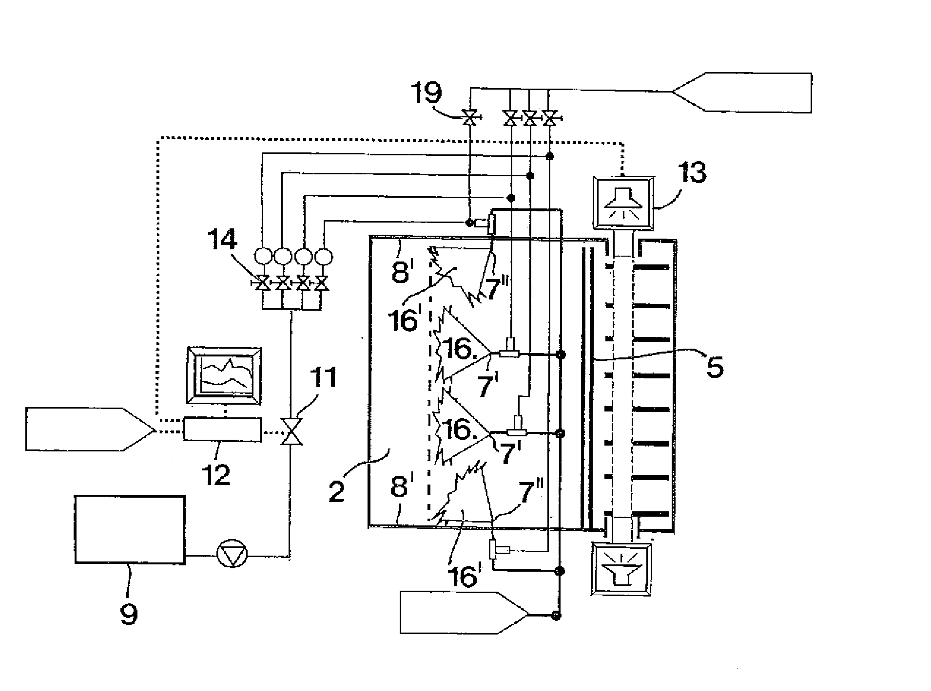
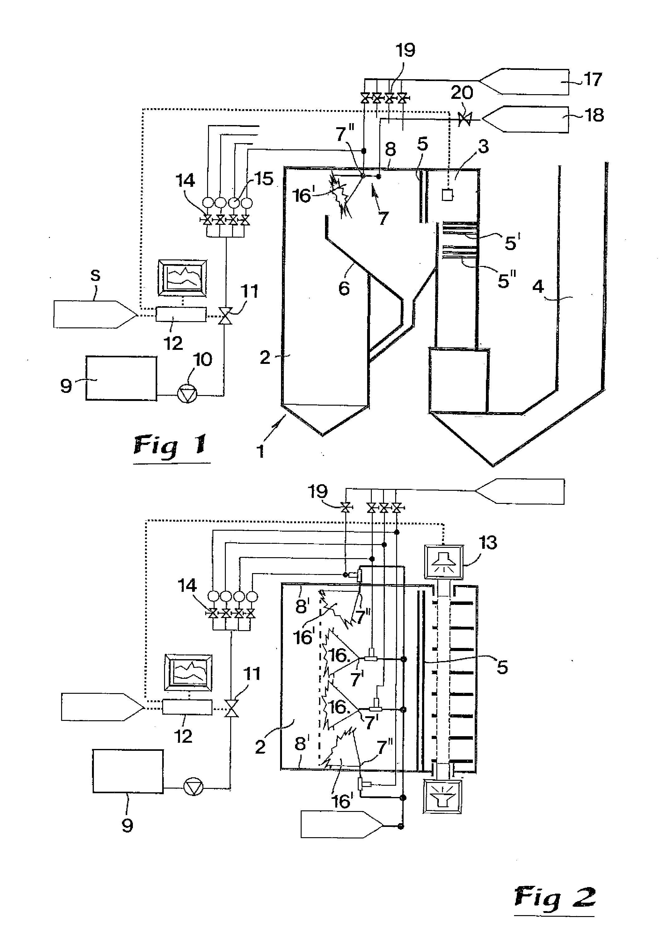
[0012]The expression “phosphorous substance” shall in this connection be understood as a substance or a composition wherein phosphor, chemically named P, is included as a product of decomposition which is released, isolated or together with other substance, within a temperature window found in a combustion plant arranged for combustion of solid fuels. The expression “combustion plant” refers to that part of a heat production plant which includes the actual combustion chamber and its extension toward and beyond heat transfer devices by which heat is withdrawn from the flue-gas. The expression “super heater” shall be understood as being encompassed in the expression heat transfer device. “Solid fuel” indicates that a main part of the fuel consists of solid material. Typical fuel examples are bio-fuel such as municipal waste, recycled wood and forest residues, or fossil fuel such as brown coal and peat, as well as here not mentioned fuel which contains chlorine that is converted to alk...


PUM

PropertyMeasurementUnit
Temperatureaaaaaaaaaa
Solubility (mass)aaaaaaaaaa

Abstract

A process for the treatment of gas phase alkaline chlorides in a combustion plant that is arranged for combustion of solid fuel and which includes a combustion chamber from which a flue-gas flow is directed to pass a heat transfer device. A phosphorous substance is added to the flue-gas flow, separate from the fuel, the substance chosen from a group of substances that form phosphorous oxide at combustion temperatures of approx. 500° C. or above, wherein the phosphorous substance is distributed in the flue-gas at a location upstream of the heat transfer device. The phosphorous substance is added to an amount which results in phosphatising of gas phase alkaline chlorides included in the flue-gas flow before the chlorides reach the heat transfer device. A corresponding combustion plant is disclosed, as well as the use of a phosphorous substance for phosphatising alkaline chloride in gaseous phase in a flue-gas flow.

Description

TECHNICAL FIELD OF THE INVENTION[0001]This invention relates in a first aspect to a process for reducing corrosion in combustion plants caused from chlorine in alkaline chloride which is formed in combustion of solid fuels containing chlorine, the process involving treatment for conversion of the chloride to a less corrosive composition. In a second aspect, the invention relates to a combustion plant arranged for carrying out the process. In a third aspect, the invention relates to the use of a phosphorous substance in a combustion plant for the treatment and conversion of gas phase alkaline chloride to less corrosive phosphate.BACKGROUND AND PRIOR ART[0002]It is a known problem within the circle of persons skilled in the art, that chlorine which is formed in combustion of chlorine-containing fuel leads to corrosion in combustion plants. It is commonly assumed that chlorine is transported in combustion gases in the form of gas phase alkaline chloride (in wood fuel combustion mostly ...

Claims


Application Information

Patent Timeline
IPC IPC(8): B01D53/68
CPCB01D53/68F23J2219/20F23J15/04F23J15/003C23F15/00F23G5/48
Inventor AHLMARK, MATTSBERG, MAGNUS
Owner VATTENFALL
Why Eureka
Try Eureka