Method and system for compensating for soft iron magnetic disturbances in a heading reference system

a head reference system and soft iron magnetic technology, applied in the field of methods and systems, can solve the problems of significant cost, approach that introduces significant cost, and approach that has not proved to be sufficiently cost-effective and efficient, and achieves the effect of improving compensation

Active Publication Date: 2013-12-26
INNOVATIVE SOLUTIONS & SUPPORT
View PDF9 Cites 37 Cited by
  • Summary
  • Abstract
  • Description
  • Claims
  • Application Information

AI Technical Summary

Benefits of technology

[0008]The above method of the present invention may be employed to improve the compensation of any magnetic indication heading reference system for the presence of significant soft iron magnetic disturbances which can result in errors in magnetic heading determinations, such as in aircraft systems, such as integrated standby units or other aircraft systems employing heading reference systems, as well...

Problems solved by technology

However, the accuracy of such readings can significantly be affected by the presence of local soft iron, such as from local electric circuits on board the aircraft, resulting in meaningful errors in the calculation and ultimate display of the magnetic heading relative to true magnetic north.
This can result in serious problems, such as with respect to the proper guidance of the aircraft along its designated flight path.
Because of the seriousness of this problem, as well as the desire for a cost effective and efficient solution various attempts have been made to try and avoid these affects which, while helpful, have not totally achieved the objective.
One such prior art attempt to try and avoid the effects of the local presence of soft iron which provides these undesirable magnetic disturbances, has involved carefully locating the external magnetometers i...

Method used


Image

  • Method and system for compensating for soft iron magnetic disturbances in a heading reference system
  • Method and system for compensating for soft iron magnetic disturbances in a heading reference system
  • Method and system for compensating for soft iron magnetic disturbances in a heading reference system

Examples


Embodiment Construction

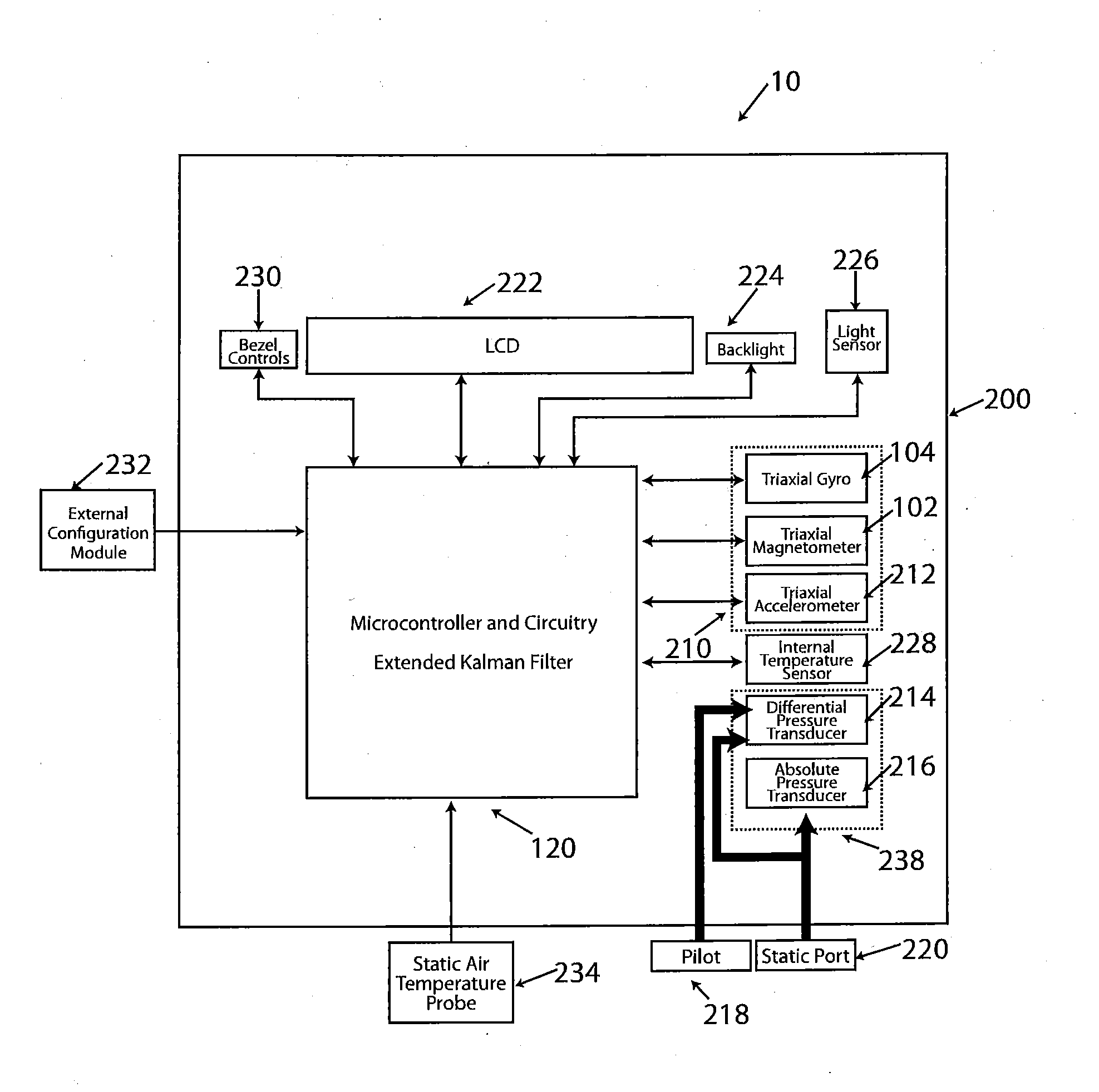
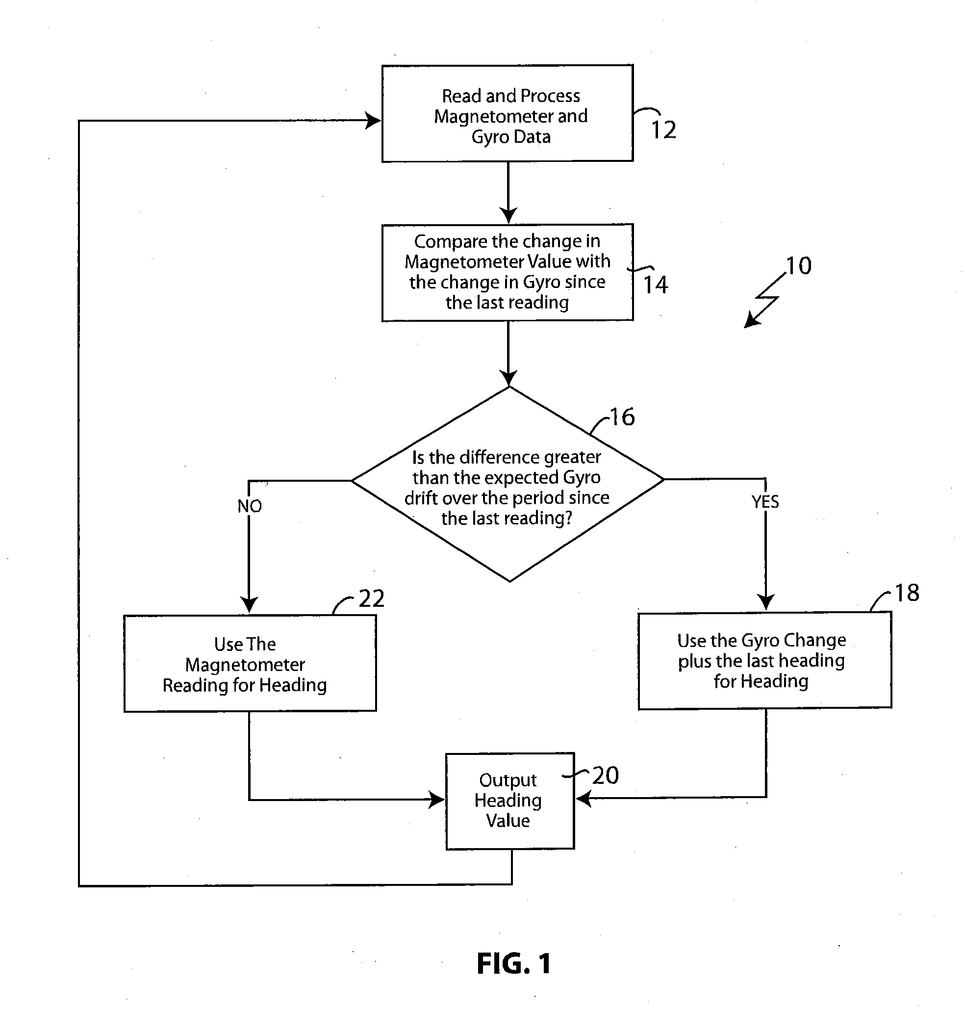
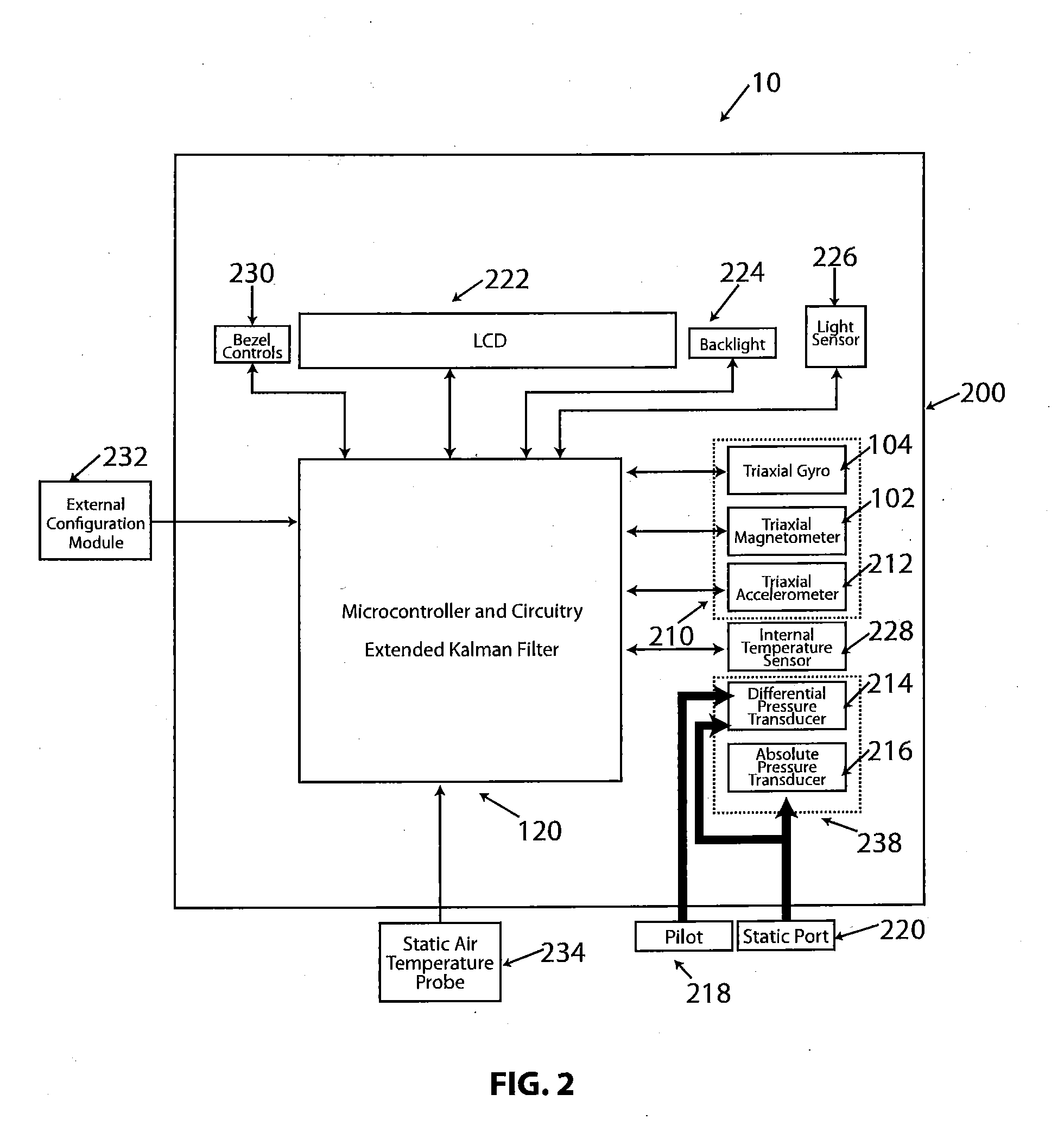
[0006]The present invention provides a method for compensating for soft iron magnetic disturbances in a heading reference system by detecting changes both in the magnetometer reading due to the presence of any soft iron magnetic disturbances and the gyro heading relative to magnetic north during a detection period, and then comparing the difference in these detected changes against a predetermined acceptable threshold value in order to determine if this difference exceeds the predetermined acceptable threshold value. If this difference exceeds the predetermined acceptable threshold value, then a heading correction signal is provided for enabling adjustment of the gyro heading in order to maintain true north in the face of the detected soft iron magnetic disturbances. If this difference does not exceed the predetermined acceptable threshold value, then the magnetometer reading is used for the heading value. The predetermined acceptable threshold value is based on the expected gyro dr...


PUM


Abstract

A method and system for compensating for significant soft iron magnetic disturbances in a heading reference system, such as an aircraft heading reference system, such as an integrated standby unit; or a vehicle inertial system, provides a heading correction signal to the heading reference system when a detected difference in value between a gyro heading relative to magnetic north and a magnetometer reading during a defined measurement period exceeds a predetermined acceptable threshold value of change, such as one based on the expected gyro drift over that period. Upon receipt of the heading correction signal, the gyro heading is adjusted to maintain an accurate heading relative to true magnetic north. If this threshold value is not exceeded, then the magnetometer reading is used for the heading value. This method is iteratively repeated in order to continually maintain an accurate heading and may be employed for each heading measurement axis.

Description

FIELD OF THE INVENTION[0001]The present invention relates to heading reference systems and particularly to such systems in which magnetic disturbances due to the presence of local soft iron can result in errors in magnetic heading determinations which affect the provision of a heading relative to magnetic north.BACKGROUND OF THE INVENTION[0002]Traditionally in heading reference systems for providing a heading relative to magnetic north, such as Attitude and Heading Reference Systems, Air Data and Attitude Heading Reference Systems, Inertial Navigation Systems, or Integrated Standby Systems of the type conventionally employed in aircraft, the heading gyro is periodically corrected by means of data from an external magnetometer that relies on the earth's magnetic field to provide a heading relative to magnetic north. However, the accuracy of such readings can significantly be affected by the presence of local soft iron, such as from local electric circuits on board the aircraft, resul...

Claims


Application Information

Patent Timeline
IPC IPC(8): G01C19/36G01C17/38
CPCG01C25/005G01C17/38G01C21/1654G01C19/36G01C21/183G01C23/005G01C23/00
Inventor ASKARPOUR, SHAHRAM
Owner INNOVATIVE SOLUTIONS & SUPPORT
Why Eureka
Try Eureka