
Method of fabricating a mechanical part, including a method of predicting the risks of crack initiation in the part in a "fretting-fatigue" situation

Active Publication Date: 2014-01-02
EUROCOPTER
View PDF1 Cites 7 Cited by
  • Summary
  • Abstract
  • Description
  • Claims
  • Application Information

AI Technical Summary

Benefits of technology

This patent describes a method to determine the conditions under which a material will crack using a test operation. The test involves applying stresses to a test piece and observing the amount of damage caused. The method selects meshes for testing that are the same size as the material being tested to increase efficiency. The results of the testing are then used to create a calibration function that corrects for any errors in the calculations. This calibration function is then used to determine the risk of crack initiation in the material based on the size and depth of the material being tested. This method is efficient, reliable, and can be used for complex and stressed materials, reducing the need for over-sizing of parts.

Problems solved by technology

Said limitation of the calculation operations must nevertheless not degrade the reliability of the prediction that is obtained, and must provide results that are satisfactory, including for parts that are complex in shape and made of a material that withstands steep stress gradients, such that a high level of stress at the surface in such a material decreases rapidly with depth.

Method used


Image

  • Method of fabricating a mechanical part, including a method of predicting the risks of crack initiation in the part in a "fretting-fatigue" situation
  • Method of fabricating a mechanical part, including a method of predicting the risks of crack initiation in the part in a "fretting-fatigue" situation
  • Method of fabricating a mechanical part, including a method of predicting the risks of crack initiation in the part in a "fretting-fatigue" situation

Examples


Embodiment Construction

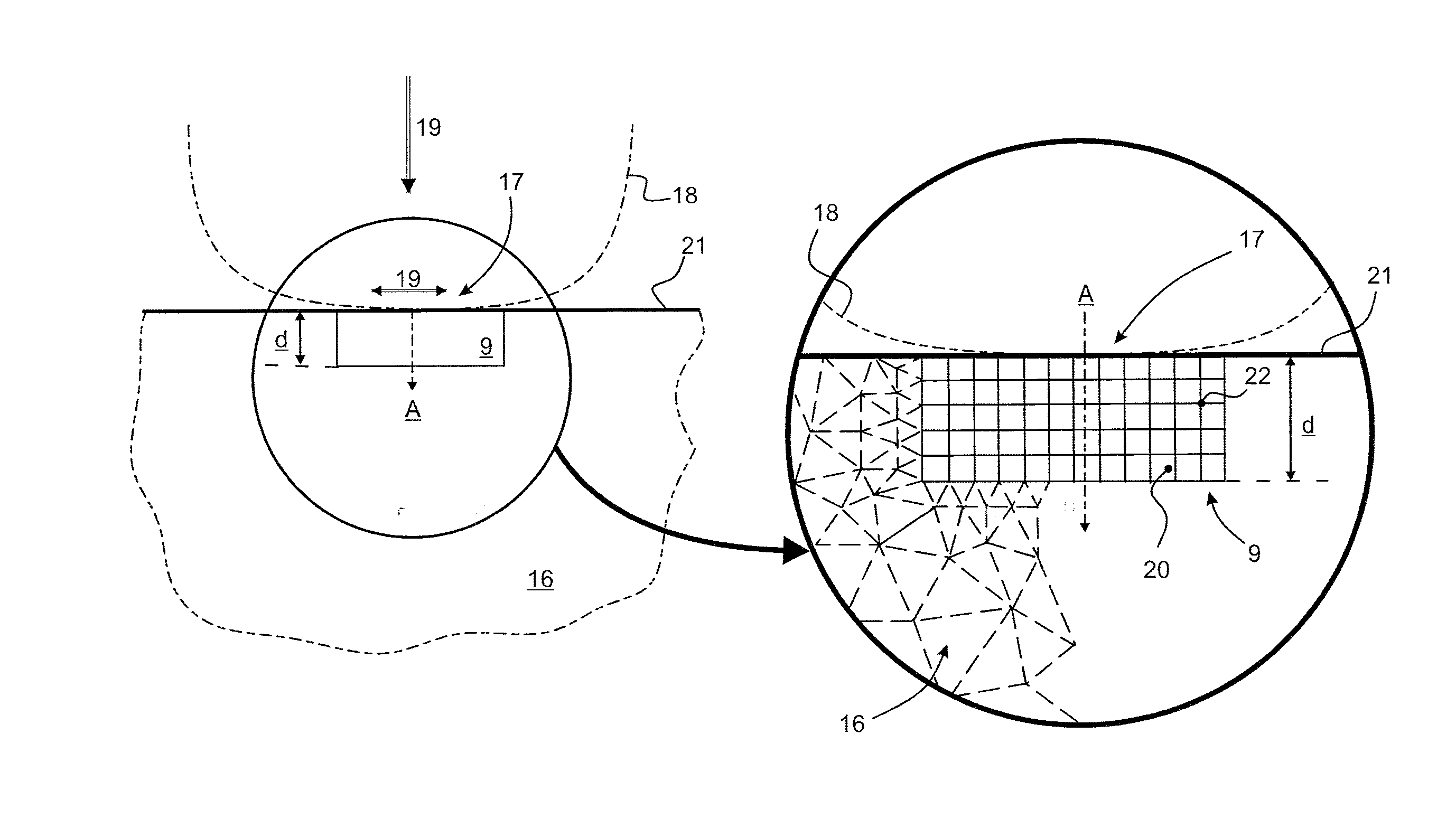
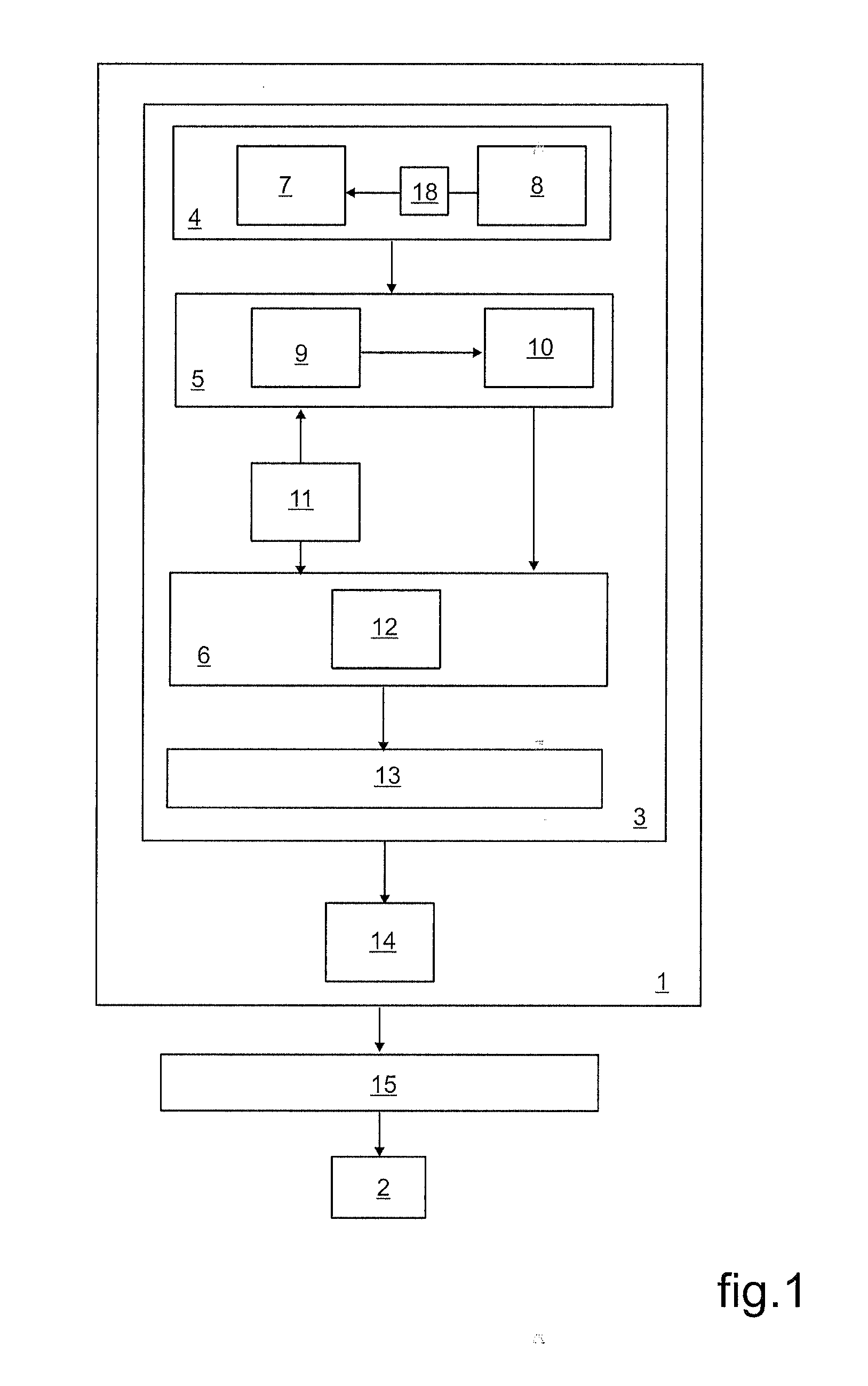
[0068]In FIG. 1, a method of fabricating a mechanical part includes an operation 1 of designing the part 2 that is to be fabricated. The design operation 1 serves to define the structure of the part 2 that is to be fabricated, by taking account of the stresses to which the part 2 that is to be fabricated will be subjected when in operation. The design operation 1 seeks to specify shapes and dimensions for the part 2 that is to be fabricated in compliance with a given material selected for making it. It should be considered that the fabrication method may implement other operations that do not form part of the techniques that are used in the context of the present invention and that are specifically dedicated to predicting the risks of cracking beginning in the part 2 that is to be fabricated.

[0069]The design operation 1 includes a predictive search 3 for the initiation of cracking in the part 2 that is to be fabricated, the search essentially involving a test operation 4 performed o...


PUM

PropertyMeasurementUnit
Lengthaaaaaaaaaa
Lengthaaaaaaaaaa
Distanceaaaaaaaaaa

Abstract

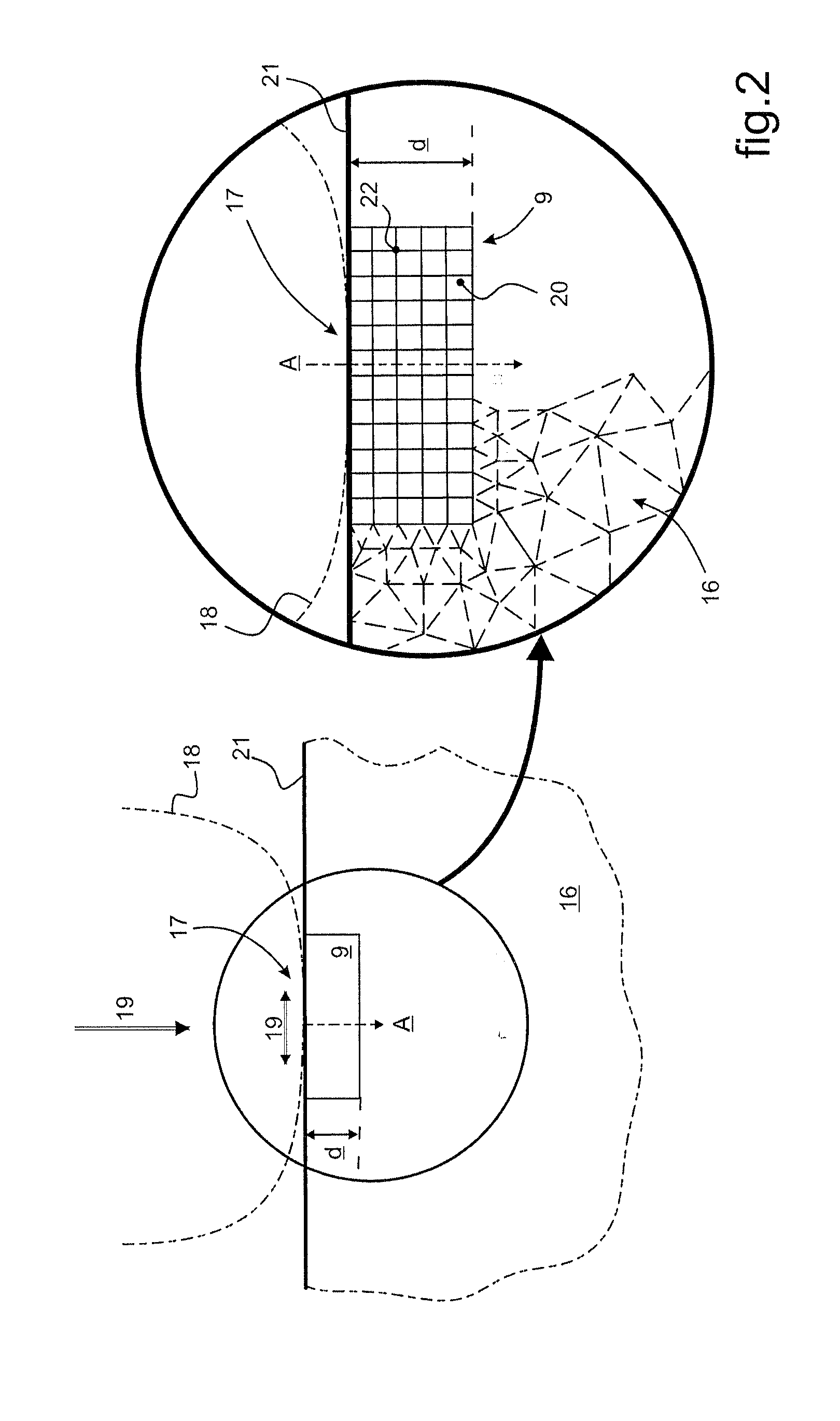
A method of fabricating a mechanical part of structure that is defined relative to a predictive search of the risks of crack initiation therein by using a method of calculation by finite elements. A coarse mesh (9) is taken into account, and the individual size of the meshes (20) and a critical distance (d) are defined jointly by an operator. The meshes (20) making up the mesh (9) are defined to be of identical mesh size, with the critical distance (d) being defined as the sum of an integer number of depth dimensions of said meshes (20). If the results of the calculation by finite elements diverge, then a calibration weighting function is advantageously applied that takes account of the size of the meshes (20) by taking account of the critical distance (d).

Description

CROSS REFERENCE TO RELATED APPLICATIONS[0001]This application claims priority to French patent application No. FR 12 01826 filed on Jun. 28, 2012, the disclosure of which is incorporated in its entirety by reference herein.BACKGROUND OF THE INVENTION[0002](1) Field of the Invention[0003]The present invention relates to the field of research into the mechanical properties of solid materials. The invention relates more particularly to searching for crack initiation conditions in a part that is to be fabricated and that is to be subjected to fretting-fatigue type stresses. Such fretting-fatigue stresses are known to associate microscopic rubbing on a surface with volume deformation such as in twisting, bending, and / or traction-compression situations.[0004]The present invention lies in the context of a method of fabricating a mechanical part, including a method of making a predictive search concerning the risks of crack initiation in said mechanical part in a fretting-fatigue situation....

Claims


Application Information

Patent Timeline
IPC IPC(8): G06F17/50G01N3/56
CPCG06F17/5018G01N3/56G01N3/32G01N2203/0062G01N2203/0064G01N2203/0218B64F5/60Y10T29/49776Y10T29/49771Y10T29/49863B21D53/92B64C2001/0081G01M5/0033G06F30/23
Inventor FOUVRY, SIEGFRIEDHEREDIA, STEPHANEBERTHEL, BRUNOGRECO, ERIC
Owner EUROCOPTER
Learn More