
Weight distribution system for seed planters and product applicators

Active Publication Date: 2014-01-02
KINZE MFG INC
View PDF38 Cites 56 Cited by
  • Summary
  • Abstract
  • Description
  • Claims
  • Application Information

AI Technical Summary

Benefits of technology

The present invention relates to a system for controlling the down force applied to planter wings in an agricultural implement. The system detects the hardness of the ground to automatically adjust the amount of down force applied, and it also allows an operator to adjust the amount based on information obtained by sensors at the toolbars, wings, and row units. The system also makes use of sensors to measure and balance wheel loading and to automatic optimize seed placement depth and minimize field compaction. This invention provides a more efficient and effective way to plan and cultivate fields.

Problems solved by technology

The process is labor intensive and time consuming, so systems have been devised whereby large centrally located seed hoppers can be bulk-filled with gravity boxes or auger seed tender systems, saving time and reducing labor.
However, the addition of the centrally located seed hoppers has created additional problems.
The additional weight has significantly increased the contact pressure of the main transport tires on the soil, causing compaction, which may result in lower crop yield.
With the weight of local seed hoppers now removed, consistency of soil penetration and furrow depth in hard soil, especially in no-till soil is compromised.
The down force has led to yet another problem.
The down force has created lift on the tool bar, on which row units are mounted, lowering ground engaging force and tire contact pressure on the ground, which results in slippage of traction-drive tires on the surface of the ground.
The change can result in planting skips or inconsistent spacing, which can adversely affect crop yield.
As a field may include varying ground hardness and conditions, the amount of down force applied in one area may not be appropriate for other areas.
Thus, a field will not be planted consistently, which would affect the overall crop yield for the field.

Method used


Image

  • Weight distribution system for seed planters and product applicators
  • Weight distribution system for seed planters and product applicators
  • Weight distribution system for seed planters and product applicators

Examples


Embodiment Construction

[0034]The contents of U.S. application No. 13 / 458,012, filed Apr. 27, 2012, U.S. application No. 13 / 457,815, filed Apr. 27, 2012, and U.S. application No. 13 / 457,455, filed Apr. 27, 2012, are all incorporated herein by reference in their entirety.

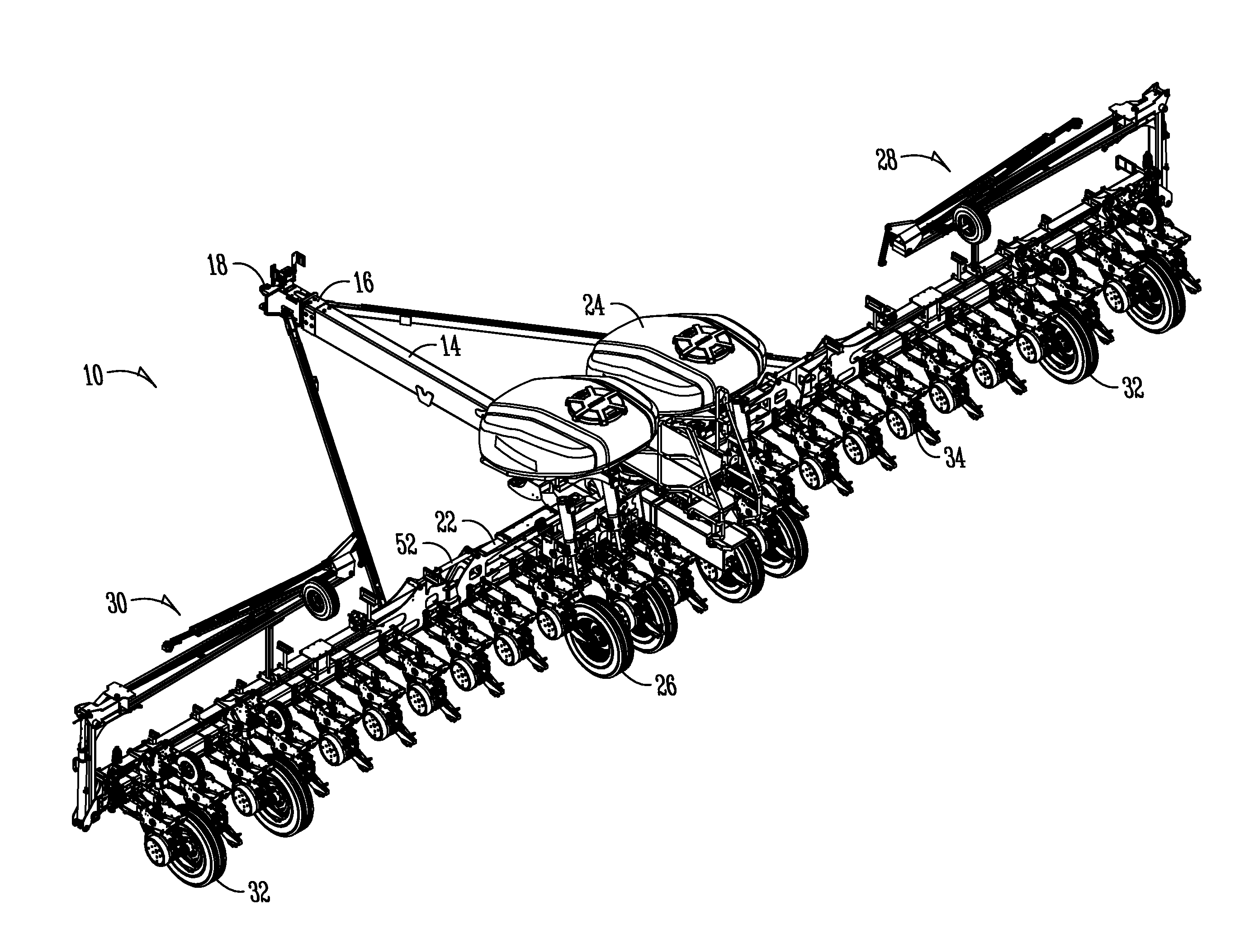
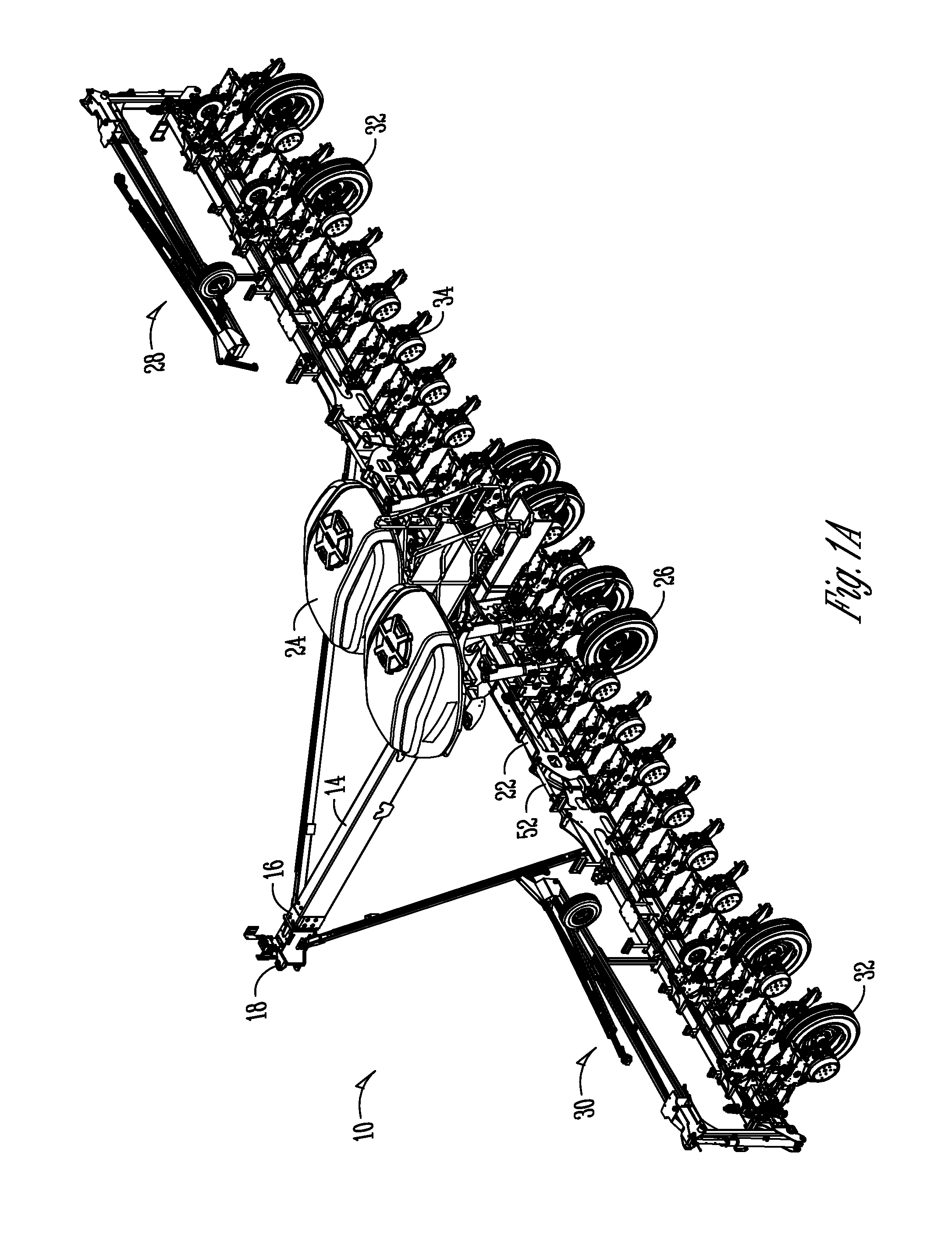
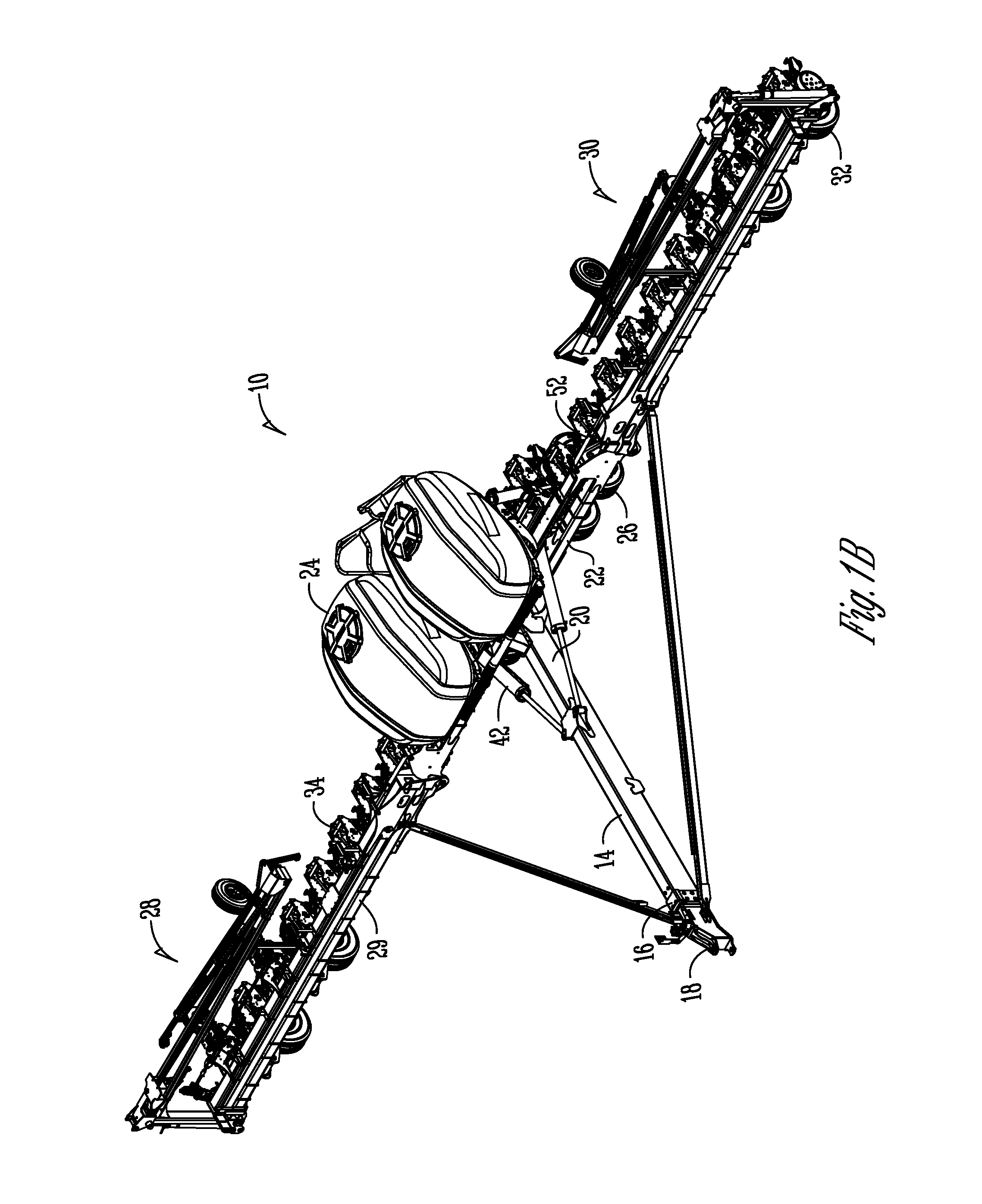
[0035]FIGS. 1A, 1B, and 2-4 show an agricultural implement 10, in this case, a planter for use with a system according to the present invention. The implement 10 may be a planter, fertilizer, or the like, and is usually attached to and pulled by a tractor 12.

[0036]However, it should be appreciated that other equipment and / or vehicles may move the implement 10. For purposes of the present disclosure, the implement 10 will be referred to as a planter. FIG. 2 shows a rear elevation view of the implement 10.

[0037]The implement 10 includes a tongue 14 having a first end 16 and an opposite second end (not shown). The tongue 14 includes a hitch 18 at the first end 16, with the hitch 18 being connected to the tractor 12. At the second end 20 of the...


PUM


Abstract

An agricultural implement is provided having a tongue, a central toolbar extending from the tongue, and first and second wings extending generally outwardly from the central toolbar. The implement may include a central hopper system to provide the material to individual row units along the central toolbar and wings, or may include individual hoppers located at each of the row units along the toolbars. A weight distribution system is used with the implement to update and adjust the amount of down force applied at the outer toolbars or wings, and the individual row units. The distribution system includes an intelligent control connected to sensors and cylinders. Therefore, the intelligent control receives information from the sensors and adjusts the cylinders accordingly to provide the appropriate amount of down force and to adjust the down force on a real time basis, and can be a closed loop or open loop system.

Description

CROSS-REFERENCE TO RELATED APPLICATIONS[0001]This application claims priority under 35 U.S.C. §119 to provisional application Ser. No. 61 / 665,356, filed Jun. 28, 2012, and which is hereby incorporated in its entirety.FIELD OF THE INVENTION[0002]The present invention relates generally to the field of agricultural equipment. More particularly, but not exclusively, the invention relates to a system for distributing the weight of an implement, such as a planter, during the use of the implement.BACKGROUND OF THE INVENTION[0003]As the power of tractors and agricultural efficiency has increased, agricultural implements such as planters have increased in span, or width, to accommodate a larger number of individual row units. Planters generally include a main frame having a forward hitch assembly for drawing by a tractor and left and right wing sections pivotally attached to a portion of the main frame. The pivoting wing connections allow the wings to fold relative to the main frame for tran...

Claims


Application Information

Patent Timeline
IPC IPC(8): A01B63/24
CPCA01C7/205A01B63/24A01B73/044A01B73/04A01C7/20A01B63/114
Inventor BACHMAN, MARVINHAHN, DUSTAN
Owner KINZE MFG INC
Learn More