Liquid crystal drive method and liquid crystal display device

a driving method and liquid crystal technology, applied in static indicating devices, instruments, non-linear optics, etc., can solve problems such as insufficient transmittance, and achieve the effects of reducing transmittance, high transmittance, and fast respons

Inactive Publication Date: 2014-01-02
SHARP KK
View PDF6 Cites 14 Cited by
  • Summary
  • Abstract
  • Description
  • Claims
  • Application Information

AI Technical Summary

Benefits of technology

[0042]According to the liquid crystal driving method and the liquid crystal display apparatus of the preferred embodiments of the present invention, the liquid crystal is driven by the first pai

Problems solved by technology

On the other hand, as described in Japanese Unexamined Patent Application Publication No. 2006-523850, only liquid crystal molecules in the vicinity of the slit electrodes are rotated when the fringe electric field is generated using the slit electrodes in the liquid crystal display apparatus having the liquid crystal molecules vertically aligned (see FIG. 62), and no sufficient

Method used


Image

  • Liquid crystal drive method and liquid crystal display device
  • Liquid crystal drive method and liquid crystal display device
  • Liquid crystal drive method and liquid crystal display device

Examples


first preferred embodiment

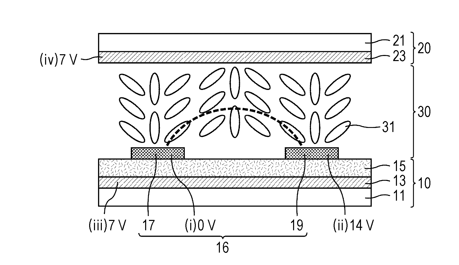
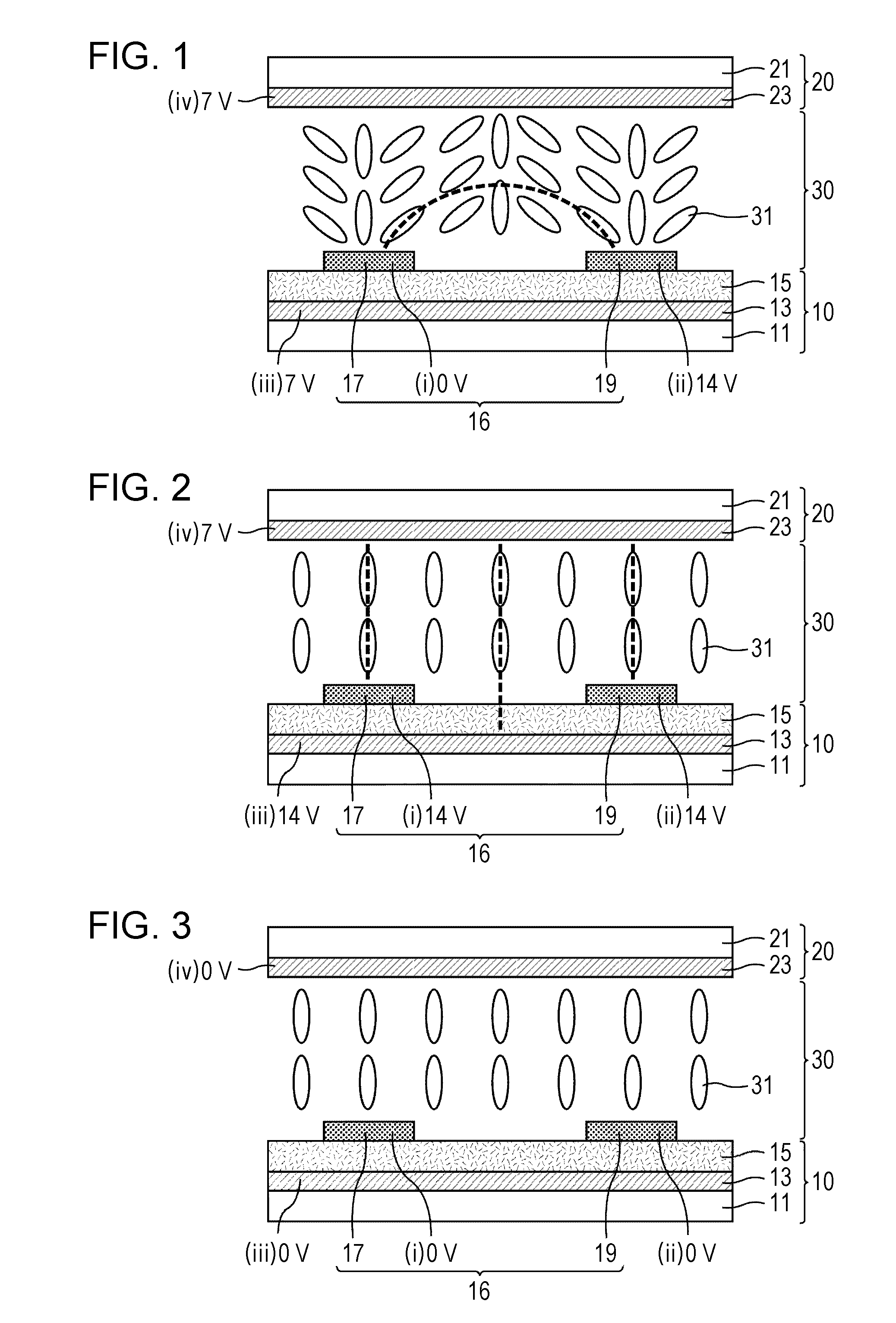
[0158]FIG. 1 is a schematic sectional view of a liquid crystal display panel of a first preferred embodiment of the present invention during the generation of an in-plane electric field. FIG. 2 is a schematic sectional view of the liquid crystal display panel of the first preferred embodiment during the generation of a vertical electric field. As illustrated in FIG. 1 and FIG. 2, a broken line indicates the direction of a generated electric field. The liquid crystal display panel of the first preferred embodiment preferably includes a vertically aligned three-layer electrode structure including liquid crystal molecules 31 as a positive-type liquid crystal (an upper layer electrode corresponding to a second layer on the lower substrate is a comb electrode). During the rise time, the in-plane electric field generated by a potential difference of about 14 V between a pair of comb electrodes 16 (preferably a comb electrode 17 having a potential of about 0 V and a comb electrode 19 havin...

second preferred embodiment

[0185]FIG. 24 is a schematic sectional view of the liquid crystal display panel of a second preferred embodiment of the present invention. FIG. 25 is a plan view of a picture element in the liquid crystal display panel of the second preferred embodiment. FIG. 26 is an equivalent circuit diagram of the picture element in the liquid crystal display panel of the second preferred embodiment. FIG. 27 illustrates a potential change of each electrode in the liquid crystal display panel of the second preferred embodiment. In the driving method of each module of the first preferred embodiment, one TFT is driven on a per picture element basis. As illustrated in FIG. 24 through FIG. 27, a chain line with two dots denotes a wiring electrically connected to a lower layer electrode on the lower substrate. A chain line with one dot denotes a wiring electrically connected to one comb electrode of the pair of comb electrodes on the lower substrate. A wiring electrically connected to the other comb e...

third preferred embodiment

[0192]FIG. 46 is a schematic sectional view of the liquid crystal display panel of a third preferred embodiment of the present invention. FIG. 47 is a plan view of a picture element in the liquid crystal display panel of the third preferred embodiment. FIG. 48 is an equivalent circuit diagram of the picture element in the liquid crystal display panel of the third preferred embodiment. FIG. 49 illustrates a potential change of each electrode in the liquid crystal display panel of the third preferred embodiment. In the driving method of each module of the third preferred embodiment, one TFT is driven on a per picture element basis. As illustrated in FIG. 46 through FIG. 49, a chain line with two dots denotes a wiring electrically connected to a lower layer electrode on the lower substrate. A chain line with one dot denotes a wiring electrically connected to one comb electrode of the pair of comb electrodes on the lower substrate. A wiring electrically connected to the other comb elect...


PUM


Abstract

A liquid crystal driving method and a liquid crystal display apparatus that achieve a sufficiently fast response, and a sufficiently high transmittance, and reduces transmittance greatly during black image displaying. The liquid crystal driving method includes performing a driving operation to cause a potential difference between a first pair of electrodes during a subframe period, a driving operation to cause a potential difference between a second pair of electrodes, and a driving operation to cause no difference between all the electrodes of the first pairs of electrodes and the second pair of electrodes.

Description

BACKGROUND OF THE INVENTION[0001]1. Field of the Invention[0002]The present invention relates to liquid crystal driving methods and liquid crystal display apparatuses. More specifically, the present invention relates to a liquid crystal driving method and a liquid crystal display apparatus that display an image by applying a vertical electric field and an in-plane electric field with a plurality of electrodes.[0003]2. Description of the Related Art[0004]A liquid crystal driving method refers to a technique of moving liquid crystal molecules in a liquid crystal layer interposed between a pair of substrates by generating an electric field between the electrodes. The liquid crystal driving method changes optical characteristics of the liquid-crystal layer, in other words, causes on and off states by either allowing a light beam to be transmitted through the liquid-crystal layer or by not allowing the light beam to be transmitted through the liquid-crystal layer.[0005]Liquid-crystal dis...

Claims


Application Information

Patent Timeline
IPC IPC(8): G02F1/1343
CPCG02F1/134363G09G2300/0495G09G3/3648G09G3/3655G09G2300/0434G09G2300/0823G09G2300/0866G09G2310/0262G02F1/134309G02F1/134381
Inventor IWATA, YOSUKEMURATA, MITSUHIRONASU, YASUHIROYOSHIDA, HIDEFUMIASAGI, HIROAKI
Owner SHARP KK
Why Eureka
Try Eureka