Motor-driven compressor

Active Publication Date: 2014-01-02
TOYOTA IND CORP
View PDF6 Cites 7 Cited by
  • Summary
  • Abstract
  • Description
  • Claims
  • Application Information

AI Technical Summary

Benefits of technology

The present invention is about a motor-driven compressor that helps cool down the electric motor near the compression unit. This improves the efficiency of the compressor and prevents damage to the motor.

Problems solved by technology

This increases the overall axial size of the motor-driven compressor.
This increases the heat generated by the coils.

Method used


Image

  • Motor-driven compressor
  • Motor-driven compressor
  • Motor-driven compressor

Examples


Embodiment Construction

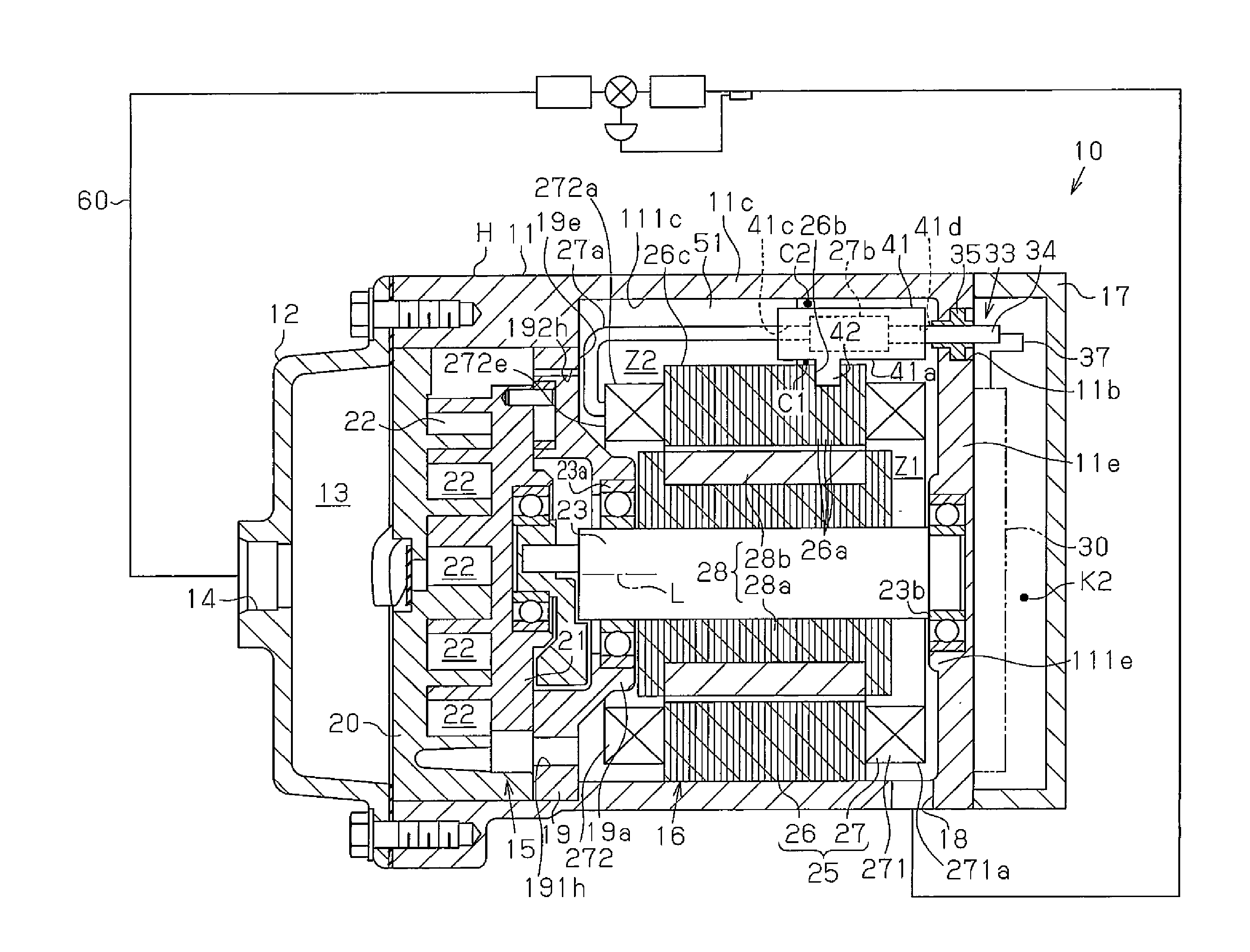
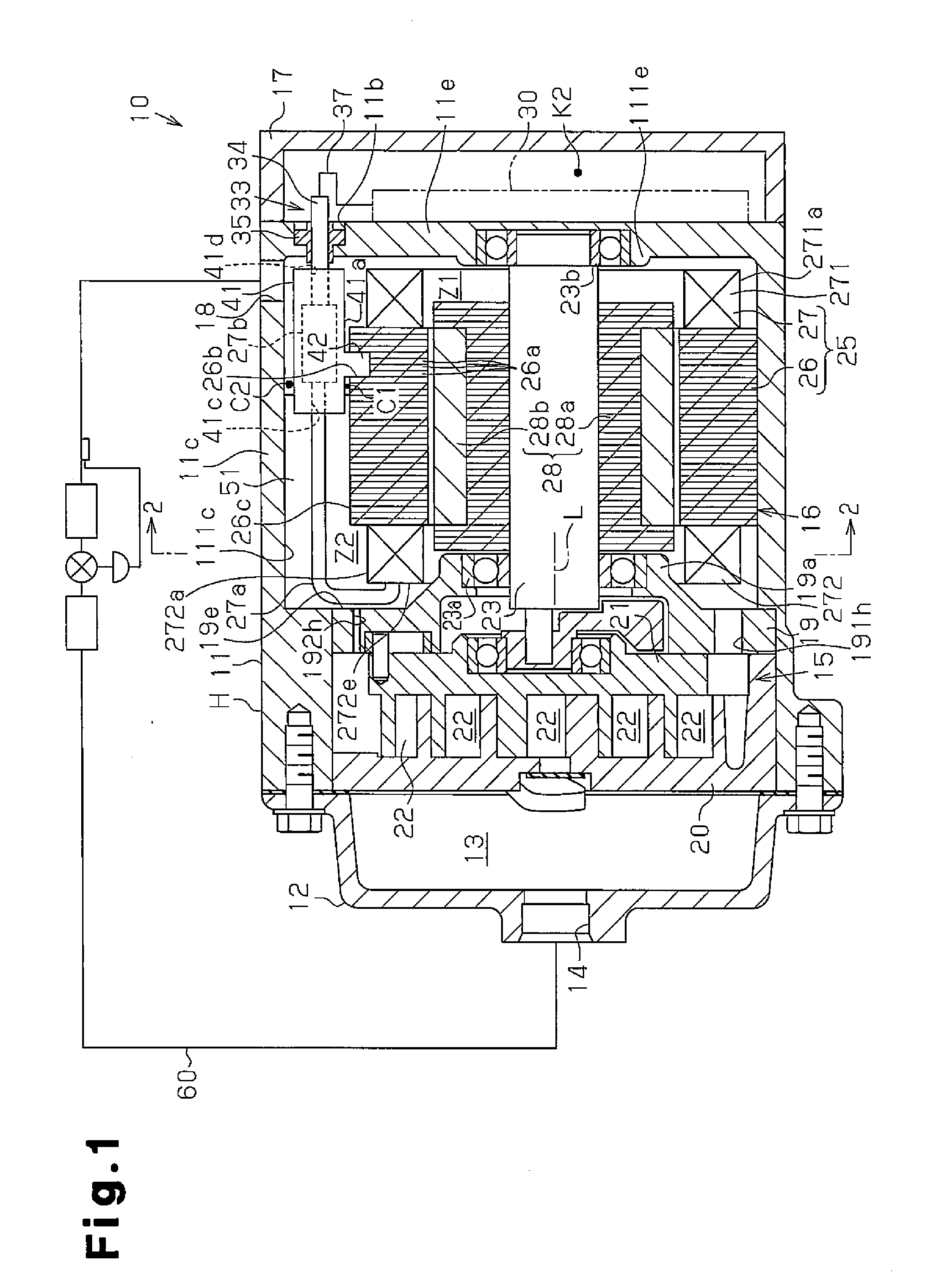
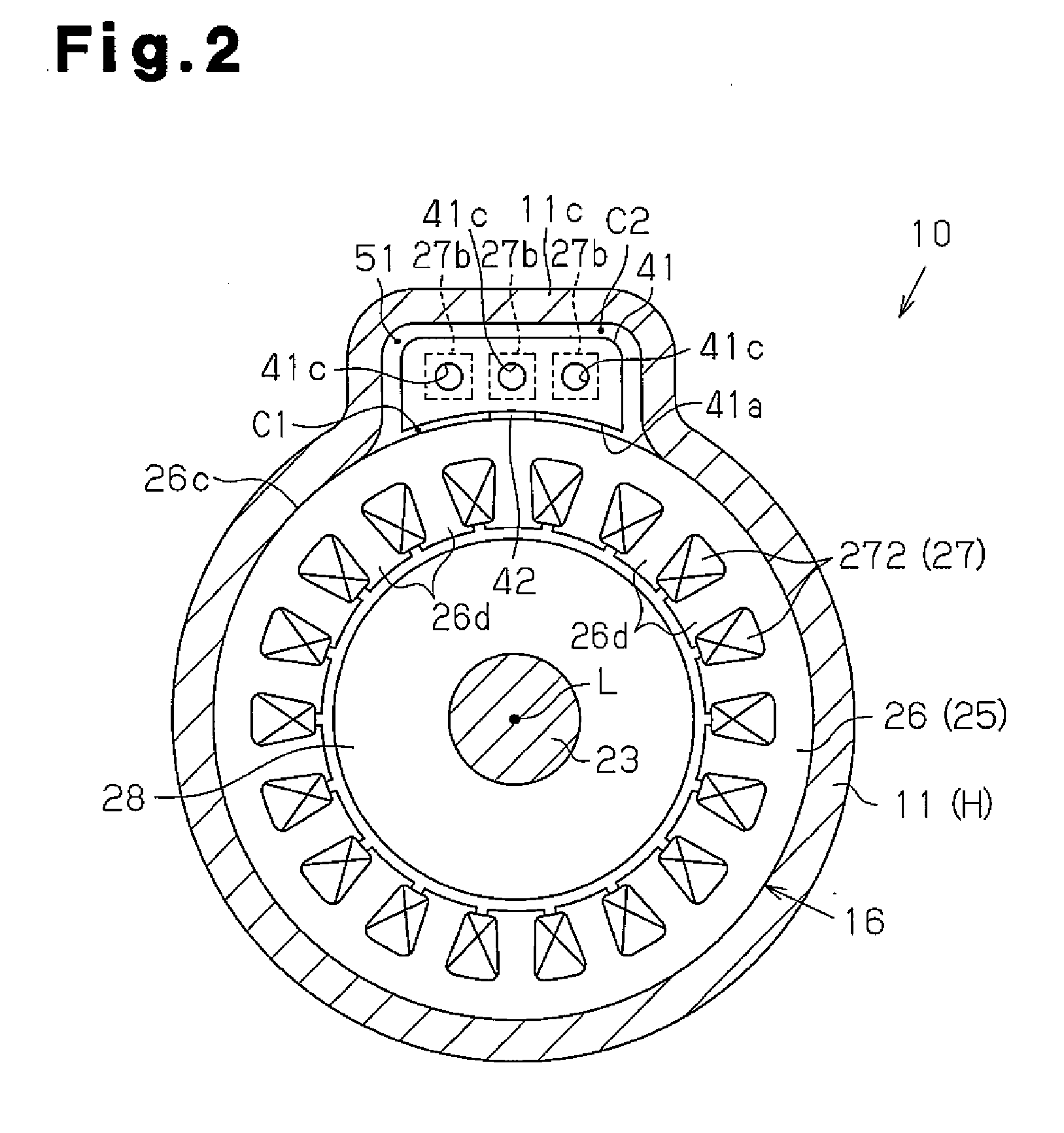
[0011]Referring to FIGS. 1 and 2, one embodiment of a motor-driven compressor for a vehicle air-conditioning device will now be described.

[0012]As shown in FIG. 1, a motor-driven compressor 10 includes a housing H that includes a motor housing member 11 and a discharge housing member 12. The motor housing member 11 is made of metal (aluminum in the present embodiment), cylindrical, and has one closed end. The discharge housing member 12 is connected to the open end (left end as indicated in FIG. 1) of the motor housing member 11. The discharge housing member 12 is made of metal (aluminum in the present embodiment), cylindrical, and has one closed end. The discharge housing member 12 forms a discharge chamber 13. The motor housing member 11 includes an end wall 11e connected to an inverter cover 17. The inverter cover 17 is made of metal (aluminum in the present embodiment), cylindrical, and has one closed end.

[0013]The motor housing member 11 accommodates a rotation shaft 23, a comp...


PUM


Abstract

A motor-driven compressor includes a compression unit having a compression chamber, a rotation shaft, an electric motor having a coil, a motor driving circuit, a housing, and a shaft support. The coil includes a first coil end, which is relatively close to the motor driving circuit, and a second coil end, which is relatively close to the compression unit. The housing includes a first area and a second area. A refrigerant passage communicates the first area with the second area. The shaft support includes a guide wall that guides the refrigerant to flow along the radial outer surface of the second coil end. The refrigerant guided by the guide wall is drawn into the compression chamber from the second area through a first suction passage. The first suction passage and the refrigerant passage are arranged at opposite sides of the rotation shaft.

Description

BACKGROUND OF THE INVENTION[0001]The present invention relates to a motor-driven compressor that includes a compression unit, an electric motor, and a motor driving circuit, which are arranged in this order along the axial direction of a rotation shaft.[0002]Japanese Laid-Open Patent Publication No. 2005-201108 discloses a motor-driven compressor. The motor-driven compressor includes a housing accommodating an electric motor and a scroll compression unit. The electric motor drives the compression unit that compresses a fluid (refrigerant). The housing includes a first fluid passage located between the outer surface of the electric motor and the inner surface of the housing. The housing also includes a partition that separates the electric motor from the fluid and guides the fluid to the first fluid passage. The partition guides the fluid drawn into the housing near the electric motor to the first fluid passage. The fluid flowing in the first fluid passage absorbs heat from the elect...

Claims


Application Information

Patent Timeline
IPC IPC(8): F04D29/58
CPCF04D29/5806F04B35/04F04B39/121F04B39/14F04B2201/0801F04C18/0215F04C29/045F04C18/02F04C29/12
Inventor FUKASAKU, HIROSHIMERA, MINORUSUITOU, KENHISHINUMA, YUMINMOROI, TAKAHIRO
Owner TOYOTA IND CORP
Why Eureka
Try Eureka