
Strakes for utility structures

a utility structure and strake technology, applied in the direction of manufacturing tools, mechanical equipment, transportation and packaging, etc., can solve the problems of vortex shedding and vibration, and the strake is not incorporated into the exterior, and achieve the effect of reducing the vibration of the vortex

Inactive Publication Date: 2014-01-09
TRINITY MEYER UTILITY STRUCTURES
View PDF9 Cites 8 Cited by
  • Summary
  • Abstract
  • Description
  • Claims
  • Application Information

AI Technical Summary

Benefits of technology

This patent describes a modular system for protecting utility structures from vibrations caused by wind and other weather factors. The system consists of fin sections that surround the structure and are attached to each other. The fins are made of sheet metal that extends outward from the structure. The attachment method involves securing individual clips to the structure and then attaching the fin sections to the clips. The system also includes a device made of welded, overlapping fin sections that helps reduce vibrations. The technical effects of this patent are improved protection of utility structures from vibrations and reduced vortex-induced vibrations.

Problems solved by technology

Due to the height of these structures, they are susceptible to dynamic wind forces that may be significant enough to result in vortex shedding and vibrations.
However, because the heavy utility structures are transported by truck and assembled at site, strakes are not incorporated into the exterior because they would be crushed.

Method used


Image

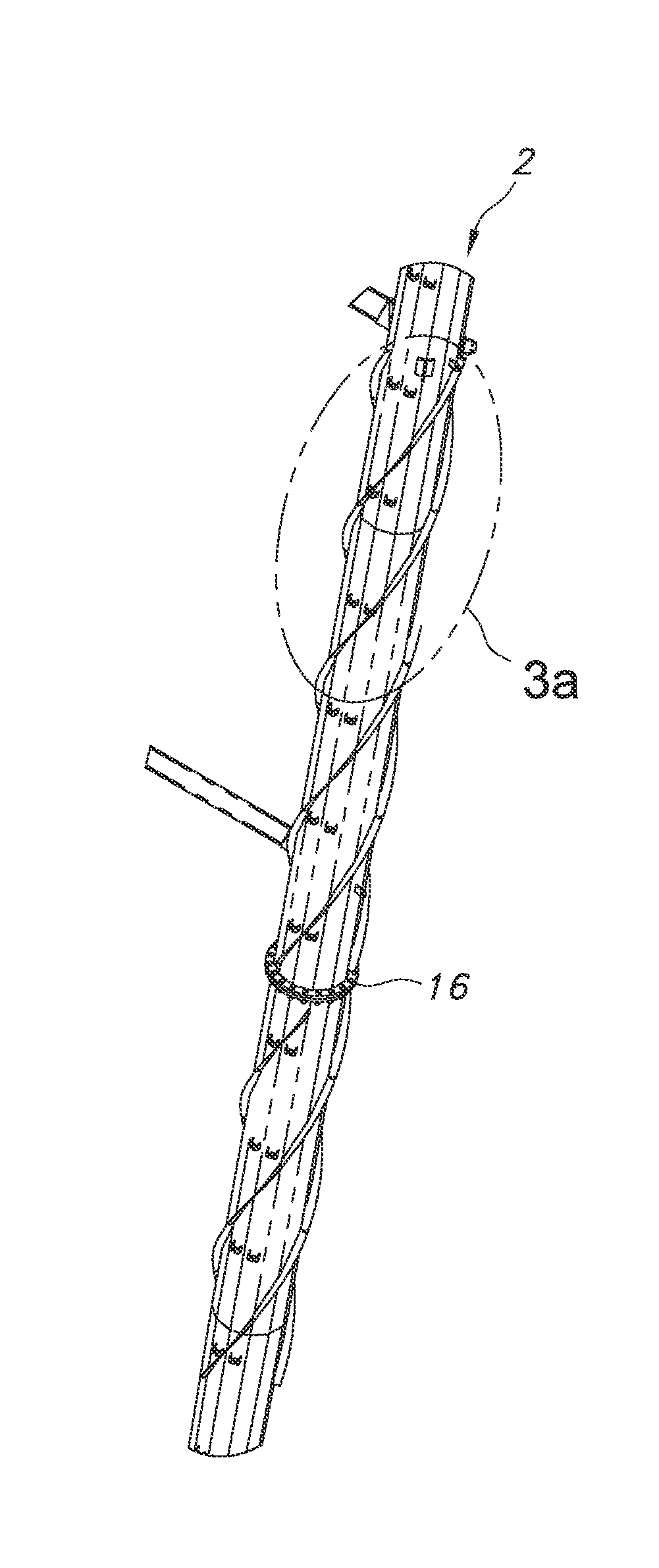
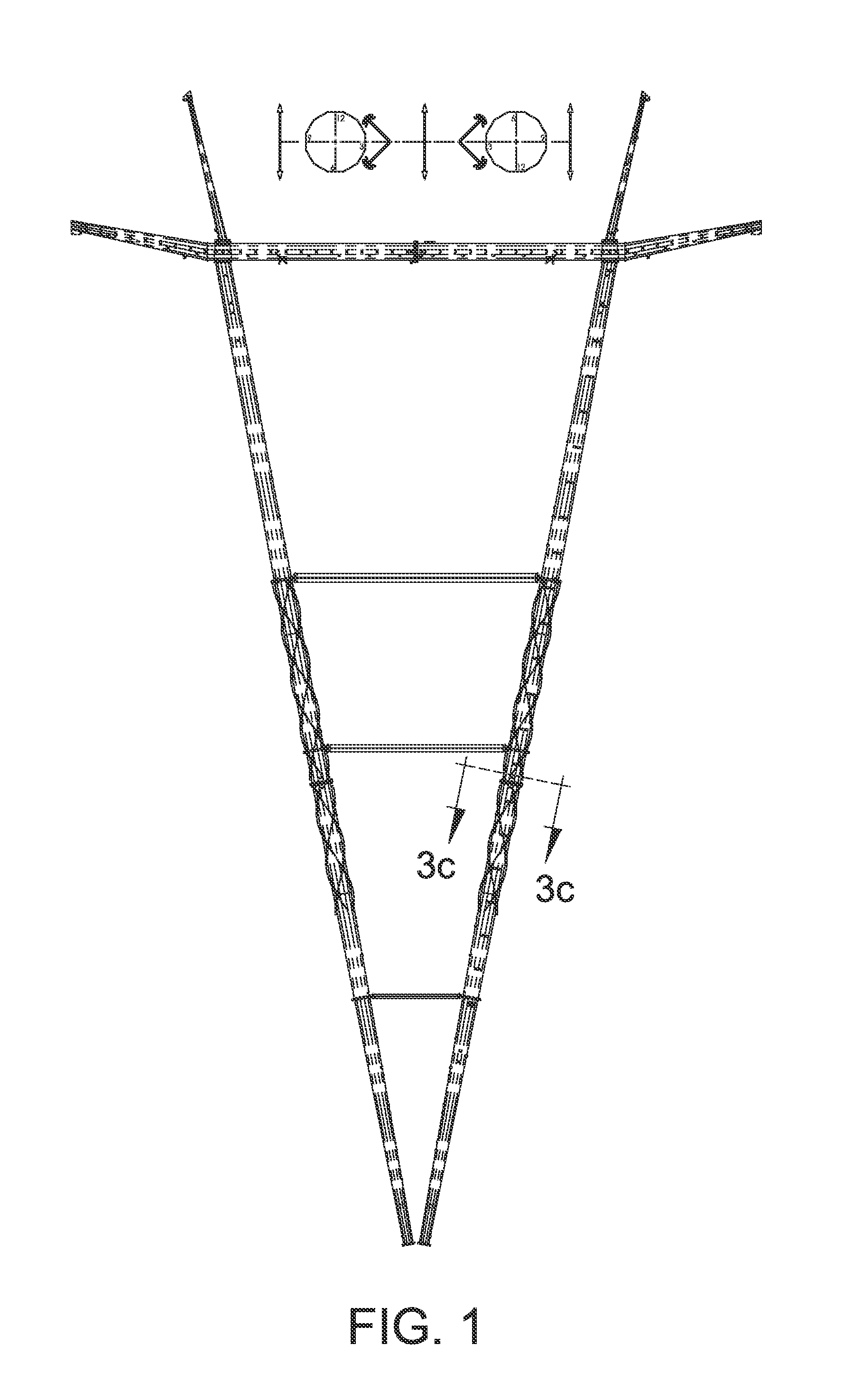
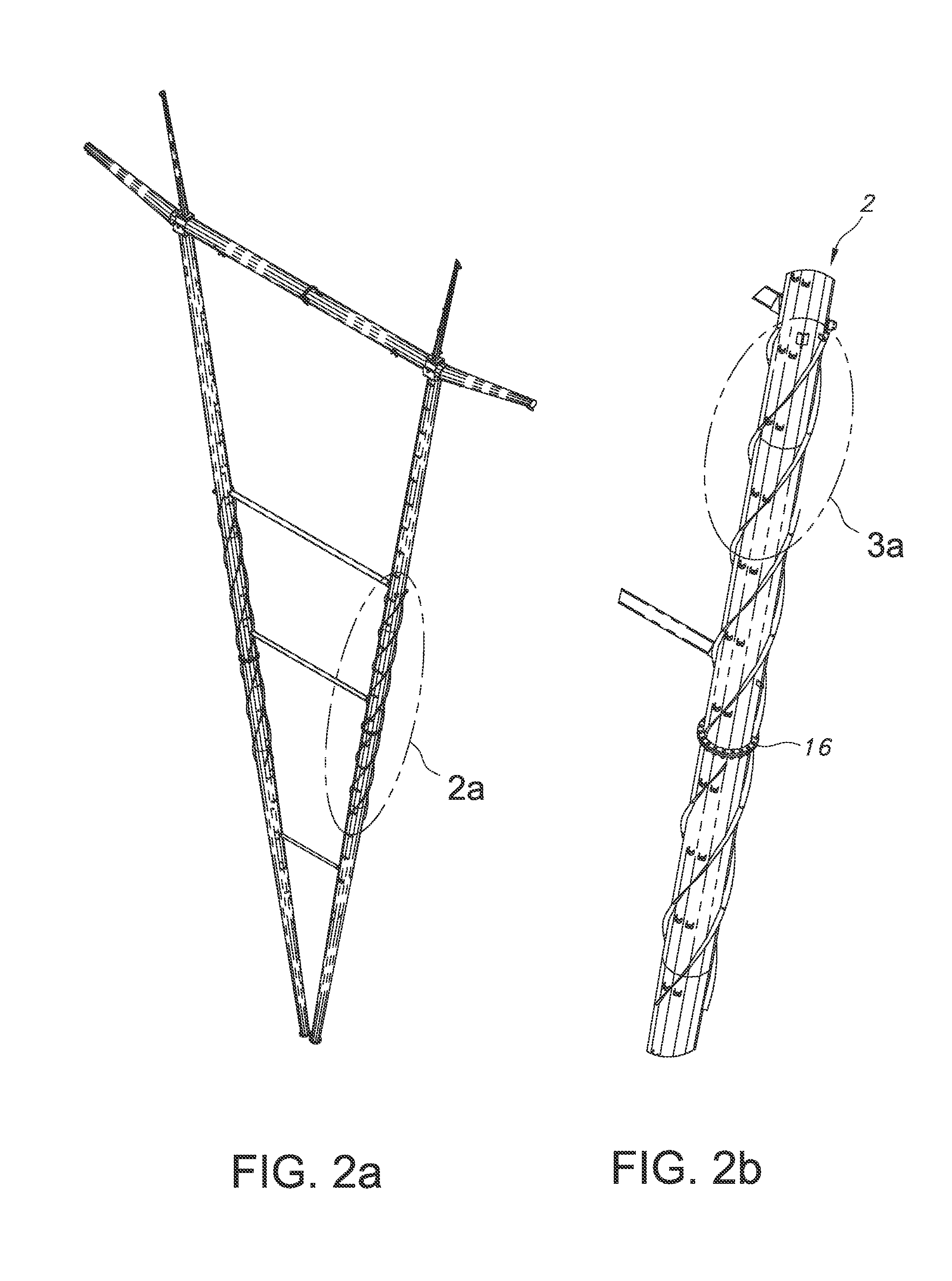
  • Strakes for utility structures
  • Strakes for utility structures
  • Strakes for utility structures

Examples


Embodiment Construction

[0022]The following detailed description is presented to enable any person skilled in the art to make and use the invention. For purposes of explanation, specific details are set forth to provide a thorough understanding of the present invention. However, it will be apparent to one skilled in the art that these specific details are not required to practice the invention. Descriptions of specific applications are provided only as representative examples. Various modifications to the preferred embodiments will be readily apparent to one skilled in the art, and the general principles defined herein may be applied to other embodiments and applications without departing from the scope of the invention. The present invention is not intended to be limited to the embodiments shown, but is to be accorded the widest possible scope consistent with the principles and features disclosed herein.

[0023]Utility structures 2 are typically elongated tubular structures comprising multiple flat sides th...


PUM

PropertyMeasurementUnit
angleaaaaaaaaaa
widthaaaaaaaaaa
perimeteraaaaaaaaaa

Abstract

A modular strake for reducing the effects of wind on utility structures is disclosed. The strake is comprised of individual fin sections that may easily be attached to a utility structure, preferably in a triple helix pattern. The modular strakes may be installed on a utility structure after is has been placed into service.

Description

FIELD OF THE INVENTION[0001]The present invention is generally directed toward a device and method for reducing vibrations due to wind or water on structures.BACKGROUND OF THE INVENTION[0002]Utility structures are used to position objects, such as cellular equipment, transmission lines and distribution lines, high above the ground. They typically incorporate at least one elongated tubular structure that is used to support the electrical lines or equipment. Due to the height of these structures, they are susceptible to dynamic wind forces that may be significant enough to result in vortex shedding and vibrations.[0003]Different methods have been used to damp the vibrations caused by the air flow on these structures. One such method of damping vibrations is by incorporating structures onto the exterior of the elongated bodies that reduce vortex shedding. For example, chimney stacks may be constructed with long helical fins, known as strakes, that interrupt the dynamic wind forces. How...

Claims


Application Information

Patent Timeline
Patent Type & Authority Applications(United States)
IPC IPC(8): F15D1/10
CPCF15D1/10E04H12/10E04H12/20H02G7/20Y10T29/49826
Inventor FAIRBAIRN, MARK HUGHPERKINS, NATHAN PAULJACOBS, EDWARD M.NAHLEN, DAVID JOSEPHSLOCUM, RICHARD MORGAN
Owner TRINITY MEYER UTILITY STRUCTURES
Learn More