
Susceptor Device And Deposition Apparatus Having The Same

a technology of a sensor device and a deposition apparatus, which is applied in the direction of chemically reactive gases, coatings, crystal growth processes, etc., can solve the problems of reducing productivity, affecting the effect of product quality, so as to reduce the speed of movement and suppress the impa

Inactive Publication Date: 2014-01-09
EPICREW
View PDF3 Cites 206 Cited by
  • Summary
  • Abstract
  • Description
  • Claims
  • Application Information

AI Technical Summary

Benefits of technology

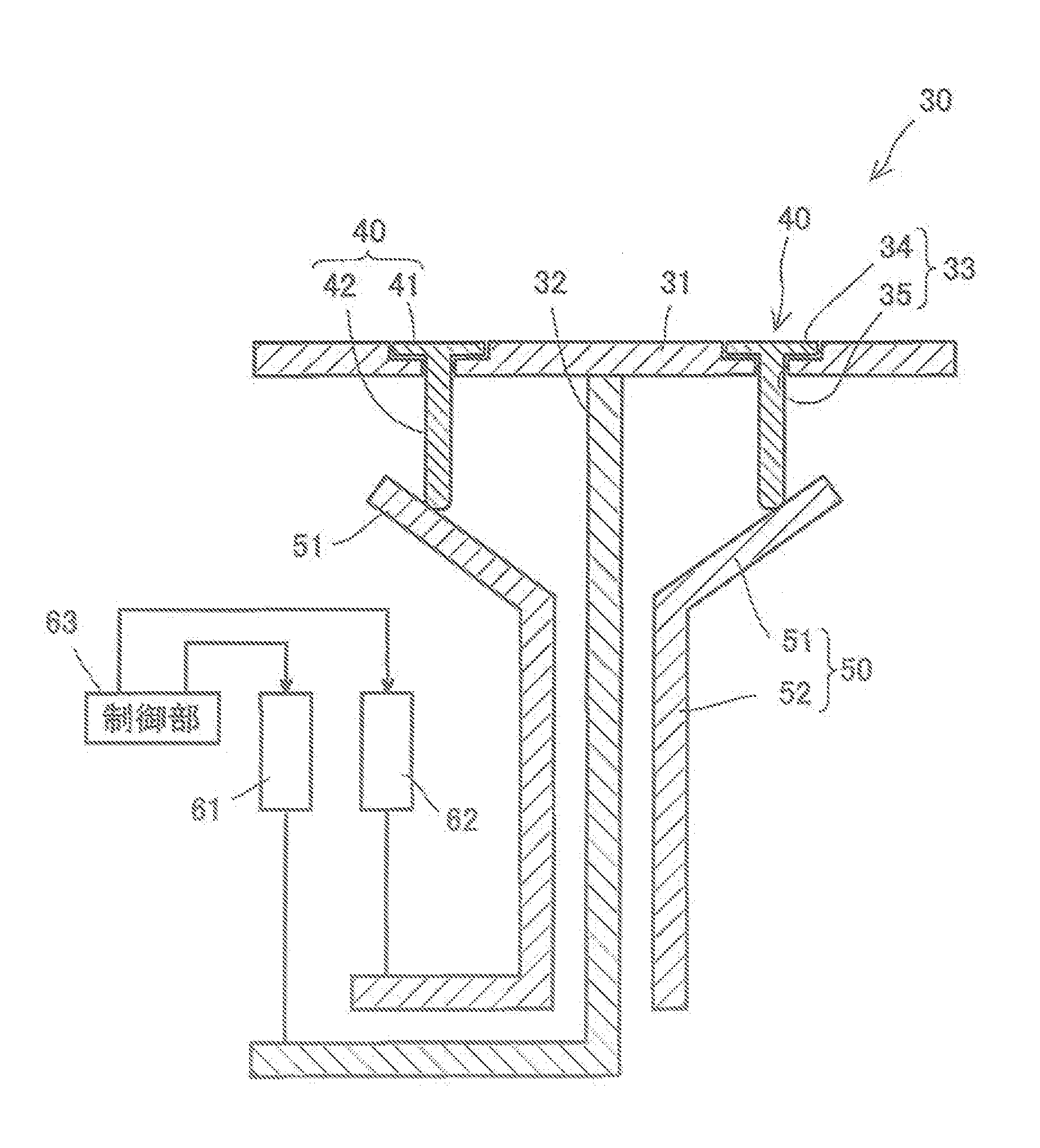
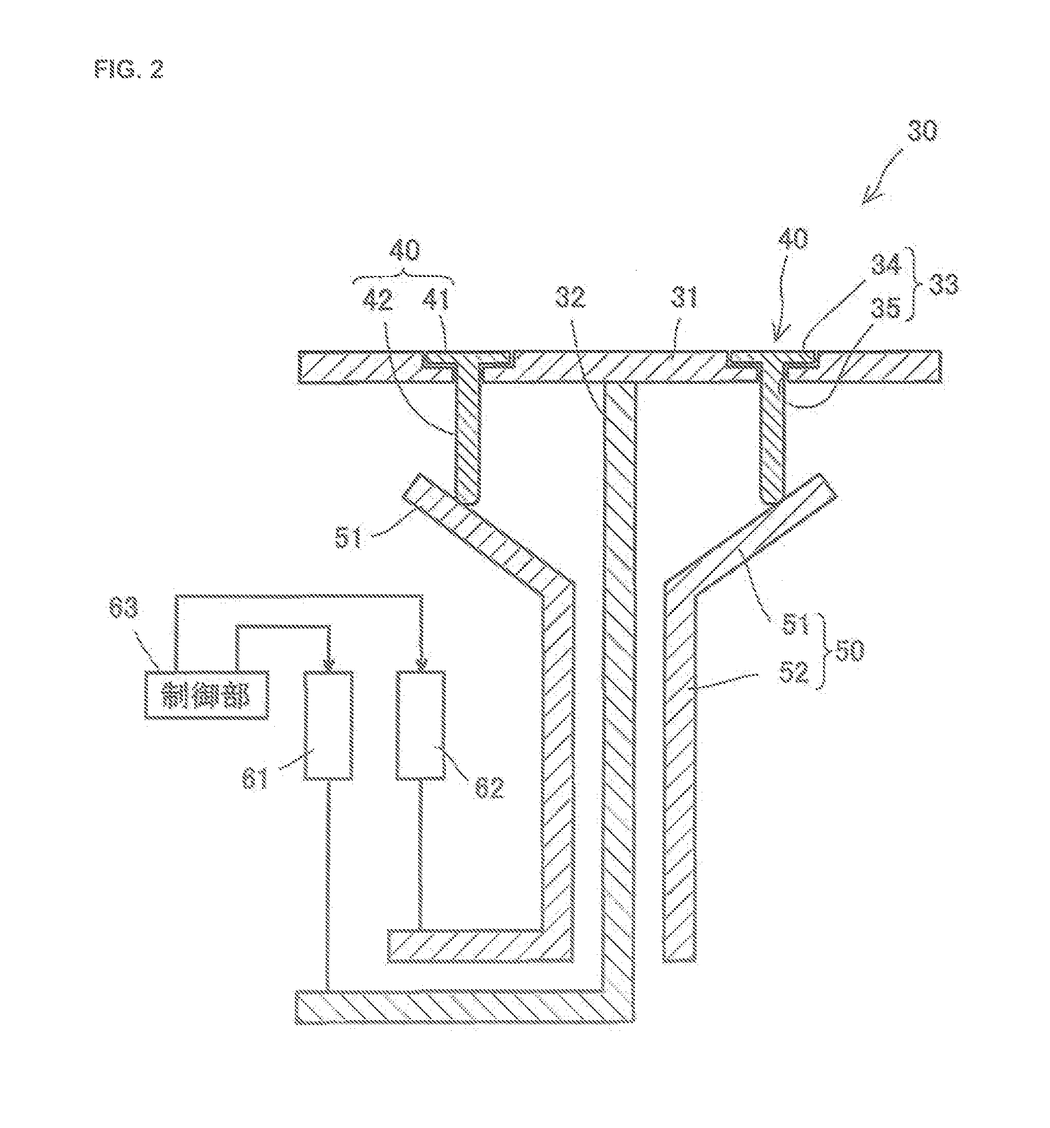
This patent is about a susceptor device used in a deposition apparatus for carrying in and out of substrates. The device includes a placement section for placing the substrate, a lift pin that supports the substrate during movement, and lift pin moving means for moving the lift pin up and down during substrate movement. The control section controls the movement of the lift pin and the placement section to reduce impact and suppress a shift in the substrate's installation position due to impact or other factors. The technical effect of this patent is to improve the deposition process while maintaining productivity by preventing damage to the substrate and ensuring accurate positioning of the substrate during movement.

Problems solved by technology

In a case of moving the substrate up and down in this manner, assuming that the substrate is moved up and down by moving the pin up and down by using an air cylinder, height adjustment of a stop position is difficult.
Further, in a case of moving the pin by the air cylinder, there is a problem in that an installation position of the substrate is shifted in a plane direction due to impact or the like at the time of contact of the pin with the substrate.
On the other hand, if up-and-down motion of the substrate is performed with a reduced movement speed in order to suppress impact at the time of contact of the pin with the substrate, productivity is reduced.

Method used


Image

  • Susceptor Device And Deposition Apparatus Having The Same
  • Susceptor Device And Deposition Apparatus Having The Same
  • Susceptor Device And Deposition Apparatus Having The Same

Examples


Embodiment Construction

[0018]A susceptor device according to the invention will be described.

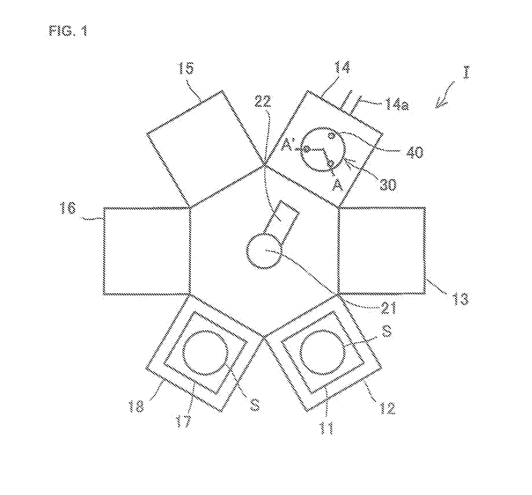
[0019]As shown in FIG. 1, a deposition apparatus I on which a susceptor device 30 is mounted is a single wafer type deposition apparatus. The deposition apparatus I includes a first load lock chamber 12 in which a first substrate cassette 11 with a substrate S for deposition stored therein is placed, a second load lock chamber 18 in which a second substrate cassette 17 is placed, and treatment chambers 13 to 16, in which each treatment which includes deposition treatment is performed. Each of the treatment chambers 13 to 16, the first load lock chamber 12, and the second load lock chamber 18 is provided with evacuation means (not shown), and it is possible to independently maintain the degree of vacuum in each chamber. In this embodiment, the treatment chamber 14 among the treatment chambers 13 to 16 is a deposition chamber in which treatment to form a film by epitaxial growth on the substrate S is performed.

[0020...


PUM

PropertyMeasurementUnit
Speedaaaaaaaaaa

Abstract

A susceptor device includes: a placement section on which a substrate is placed; a lift pin which is provided in the placement section and protrudes further to the upper side than the placement section at the time of carrying-in or carrying-out of the substrate, thereby supporting the substrate placed on the placement section; and lift pin moving means for moving the lift pin up and down. At the time of carrying-in or carrying-out of the substrate, the substrate is moved up and down by moving the lift pin up and down by the lift pin moving means in a state where the substrate is supported by the lift pin, and the susceptor device further includes a control section which controls the lift pin moving means so as to reduce a movement speed immediately before the substrate and the lift pin come into contact with each other, in a case of moving the lift pin.

Description

BACKGROUND OF THE INVENTION[0001]1. Field of the Invention[0002]The present invention relates to a susceptor device and a deposition apparatus having the same.[0003]2. Background Art[0004]Usually, in a deposition apparatus, a substrate carried into a load lock chamber carried into deposition chamber by a robot and the substrate is placed on a susceptor device. Then, a technique is known in which a tip of a pin is brought into contact with the substrate and the pin is moved up and down in this state, whereby up-and-down motion of the substrate is performed (refer to, for example, Japanese Unexamined Patent Application Publication No. 2006-41028 (Paragraph 0020 and the like)).SUMMARY OF THE INVENTION[0005]In a case of moving the substrate up and down in this manner, assuming that the substrate is moved up and down by moving the pin up and down by using an air cylinder, height adjustment of a stop position is difficult. Further, in a case of moving the pin by the air cylinder, there is...

Claims


Application Information

Patent Timeline
IPC IPC(8): C30B25/12
CPCC30B25/12C23C16/4583H01L21/68742
Inventor OKABE, AKIRATANOGUCHI, MASANORIMORI, YOSHINOBU
Owner EPICREW
Learn More