Liquid dosing devices

a technology of liquid dosing device and liquid dosing, which is applied in the direction of volume metering, single-unit apparatus, instruments, etc., can solve the problems of speed and convenience, slow recovery position of obturator, and erratic dosing,

Active Publication Date: 2014-01-09
RIEKE LLC
View PDF19 Cites 21 Cited by
  • Summary
  • Abstract
  • Description
  • Claims
  • Application Information

AI Technical Summary

Benefits of technology

[0039]A dosing device for dispensing liquid from a container in which flow through flow openings to an outlet tube is blocked after controlled delay by an obturator moveable within a control chamber mounted in a container neck behind the outlet tube. Movement of the obturator is governed by restricted flow through control openings at the rear of the control chamber. Restoration of the obturator to the back of the control chamber facilitates repeated dosing. An elastomeric element of resiliently deformable material promotes a seal to achieve a cleanly defined dose. In one proposal the elastomeric element coats the surface of the obturator and / or the outlet tube to cut off the flow. Another proposal provides a one-way elastomeric valve element for blocking the flow openings to enable rapid recovery after a dosing operation.

Problems solved by technology

However there are issues with speed and convenience.
Obturators may be slow to recover position, and the dispenser needs to be returned to an upright position to create a new dose or restart the mechanism.
However, it was learned that dosing was both difficult and erratic.
It has now been learned that this problem was due to the disposition and material of the valve flap.
It was also learned that there existed a problem of dripping or trickling before a first dose and between repeated doses when the container was inverted, so that repeated dosing while inverted was not of satisfactory quality.

Method used


Image

  • Liquid dosing devices
  • Liquid dosing devices
  • Liquid dosing devices

Examples


third embodiment

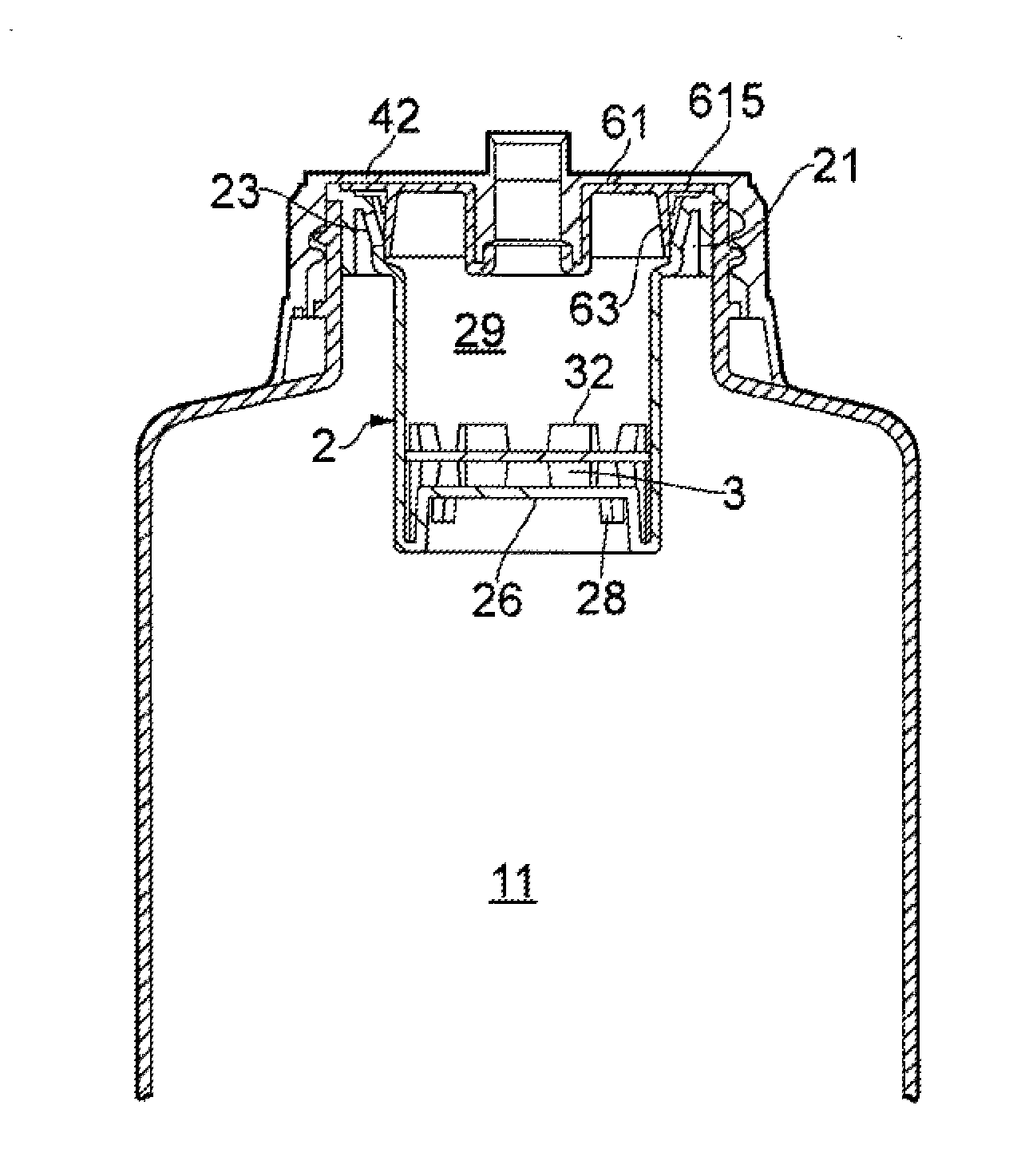
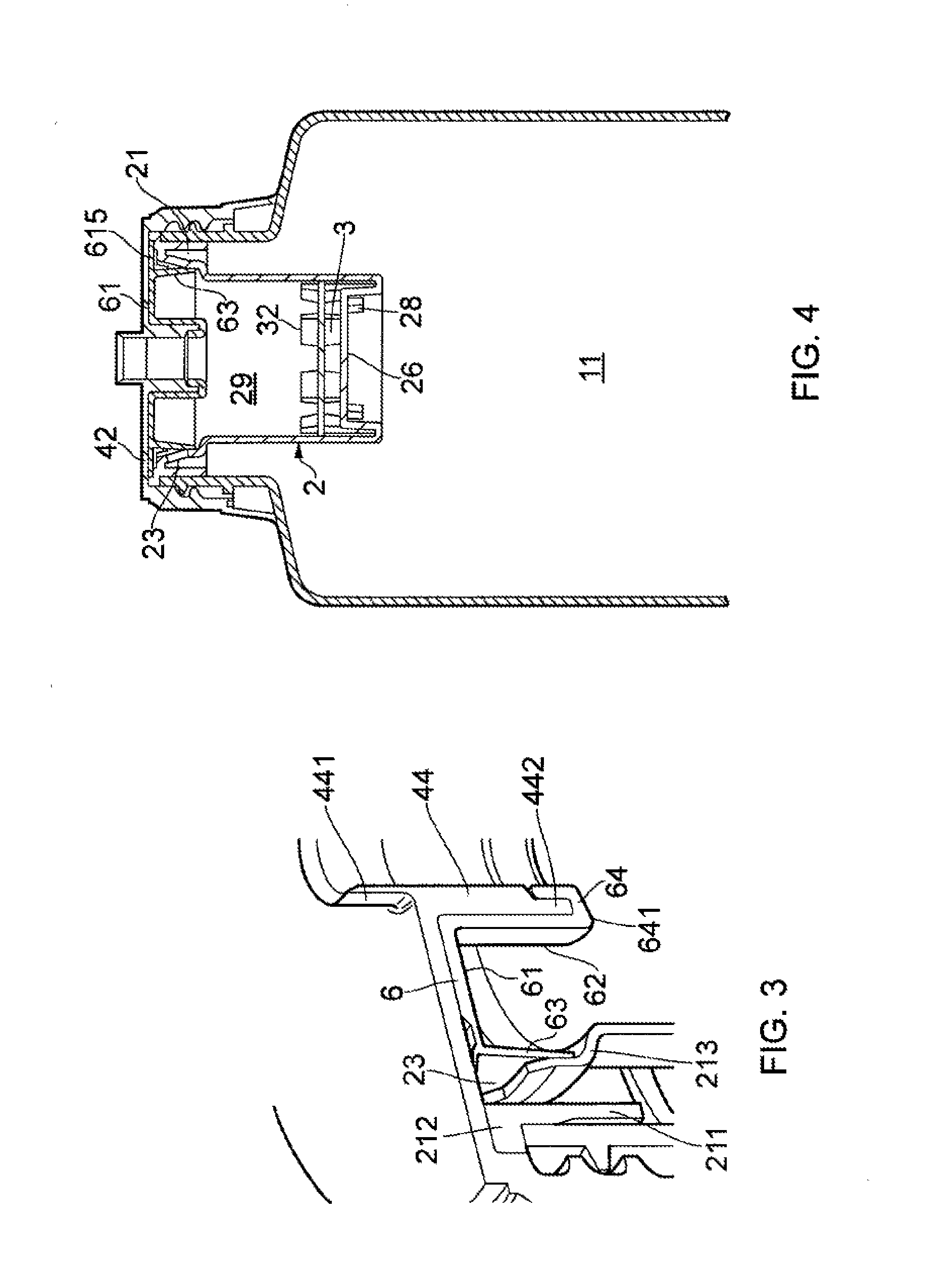
[0062]FIGS. 5 and 6 show a third embodiment in which the control chamber 2, control piston 3 and cover cap 4 are the same as in the first two embodiments. Here however the elastomeric valve insert 106 provides the anti-reverse and non-drip functions, but does not provide the elastomeric seat for the control piston. Thus, the elastomeric insert 106 has the front base web 161 with a simple central hole to fit around the outlet tube 44 of the front cap, extending out to the trapped outer flange 1615 as before, and projecting rearwardly with the outwardly-flaring annular sealing lip 163. As in the previous embodiments, the sealing lip 163 seals outwardly against the inwardly-directed surface of the forwardly outwardly-flaring mounting structure 213 of the control cylinder 2, which also defines the flow openings 23 (see FIG. 5). Also as in the previous embodiments the sealing lip 163 is pre-loaded or bias against the counter-surface. That is, the elastomeric insert 106 in the free as-mol...

fourth embodiment

[0063]FIGS. 7 and 8 show a Here the container 10 and control piston 3 are the same as in previous embodiments, but the control cylinder 102, front cap 104 and sealing insert 206 are slightly different. Firstly, the control cylinder defines the flow openings 123 through an axially-directed wall or face 124 diverting perpendicularly out from the cylindrical wall of the chamber 102, and meeting the outer mounting annulus 121 perpendicularly. To seal these axially-facing flow openings 123, an axially-operating valve member is needed. In this embodiment it is provided by annular valve insert 206, made from elastomer in one piece as in the previous embodiments. In this embodiment the sealing element or flap 263 is a flat annulus, connected to a central mounting sleeve 262 by a set of integral spokes or legs in the manner of a wheel. The front plate of the cover cap has a rearwardly-projecting skirt 140 concentric with and close to the outlet tube 44, defining a circular notch in to which...


PUM


Abstract

A dosing device for dispensing liquid from a container (1) in which flow through flow openings (23) to an outlet tube (44) is blocked after controlled delay by an obturator (3) moveable within a control chamber (2) mounted in a container neck (101) behind the outlet tube (44). Movement of the obturator (3) is governed by restricted flow through control openings (28) at the rear of the control chamber. Restoration of the obturator to the back of the control chamber facilitates repeated dosing. An elastomeric element (6) of resiliently deformable material promotes a seal to achieve a cleanly defined dose. In one proposal the elastomeric element coats the surface of the obturator and / or the outlet tube (64) to cut off the flow. Another proposal provides a one-way elastomeric valve element (63) for blocking the flow openings to enable rapid recovery after a dosing operation.

Description

CROSS REFERENCES TO RELATED APPLICATIONS[0001]This application is a continuation-in-part of U.S. patent application Ser. No. 13 / 036,252 filed Feb. 28, 2011, which is a continuation of International Application PCT / GB2009 / 002106, filed Sep. 1, 2009, which claims the benefit of Great Britain Application No. 0815881.8, filed Sep. 1, 2008, the entire disclosures of which are hereby incorporated by reference.BACKGROUND OF THE INVENTION[0002]This invention has to do with devices adapted for dispensing metered doses of liquid from a container, and containers incorporating such devices, and methods of using them. In preferred embodiments the devices are used in, or adapted for use in, squeezable containers, especially resiliently-shape-recovering squeezable containers. A preferred field of use is that of containers for domestic or household use, containing detergents or other cleaning preparations, fabric conditioners, or liquid foods such as sauces.[0003]Particularly, the invention is conc...

Claims


Application Information

Patent Timeline
Patent Type & Authority Applications(United States)
IPC IPC(8): B65D47/00
CPCB05B11/048G01F11/263G01F11/082B65D47/0838B05B11/04G01F11/04B65D47/2018
Inventor LAW, BRIAN ROBERTSPENCER, JEFFREY WILLIAMPRITCHETT, DAVID JOHN
Owner RIEKE LLC
Why Eureka
Try Eureka