Eureka AIR delivers breakthrough ideas for toughest innovation challenges, trusted by R&D personnel around the world.

High efficiency optic

a high-efficiency, optics technology, applied in the field of ophthalmic lenses, can solve the problems of affecting vision quality, affecting the ability of presbyopic eyes to quickly and easily refocus on objects, and crystalline lenses that have only limited ability to change shape, so as to reduce light scatter, improve light energy distribution, and reduce the effect of light scatter

Active Publication Date: 2014-01-09
JOHNSON & JOHNSON SURGICAL VISION INC
View PDF2 Cites 29 Cited by
  • Summary
  • Abstract
  • Description
  • Claims
  • Application Information

AI Technical Summary

Benefits of technology

The present invention provides better lenses and imaging techniques for the eye. It offers monofocal and multifocal lenses with reduced light scatter and improved energy distribution. By designing the lens with a controlled curvature, the invention limits the harmful light energy directed to certain orders, reducing dysphotopsia. Additionally, the invention also limits scatter effects that might occur with conventional diffractive lenses. Overall, the invention improves vision quality with lenses that provide better optical performance.

Problems solved by technology

The presbyopic eye often loses the ability to rapidly and easily refocus on objects at varying distances.
By the age of 65 years, the crystalline lens has often lost almost all elastic properties and has only limited ability to change shape.
Along with reductions in accommodation of the eye, age may also induce clouding of the lens due to the formation of cataracts.
For multifocal lenses, along with directing portions of the incident light energy at focal distances suitable for near and far viewing, diffractive optics may also direct significant light energy at other non-viewing foci, which can contribute to unwanted light-related visual phenomenon experienced by the patient (dysphotopsia).
Having non-viewing foci of diffractive optics of multifocal lenses cannot be completely avoided.

Method used


Image

  • High efficiency optic
  • High efficiency optic
  • High efficiency optic

Examples


Embodiment Construction

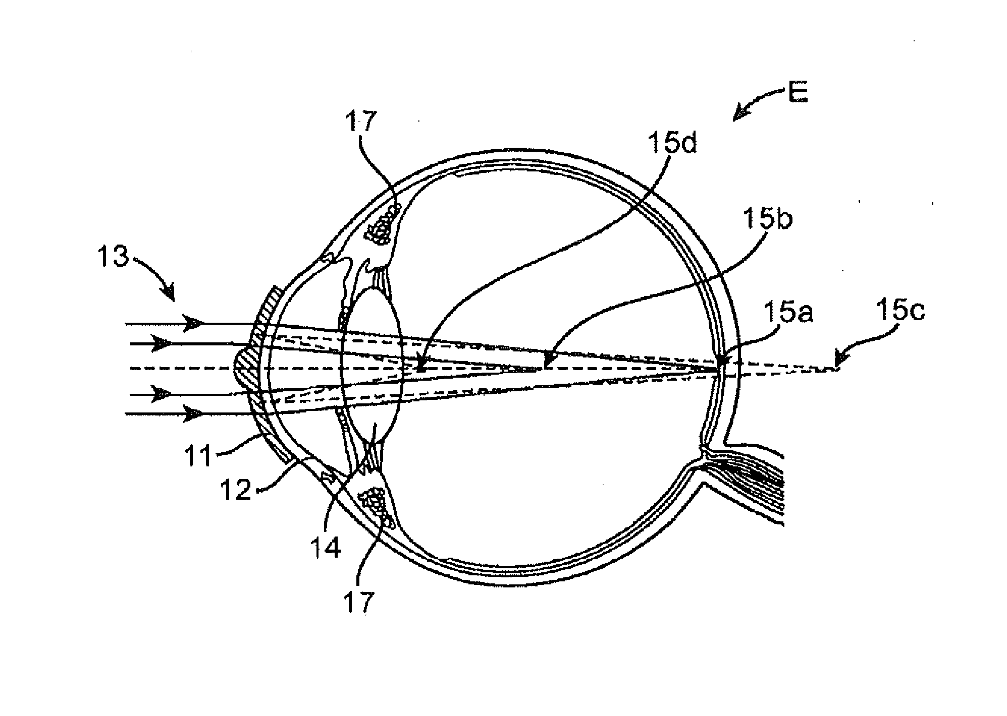
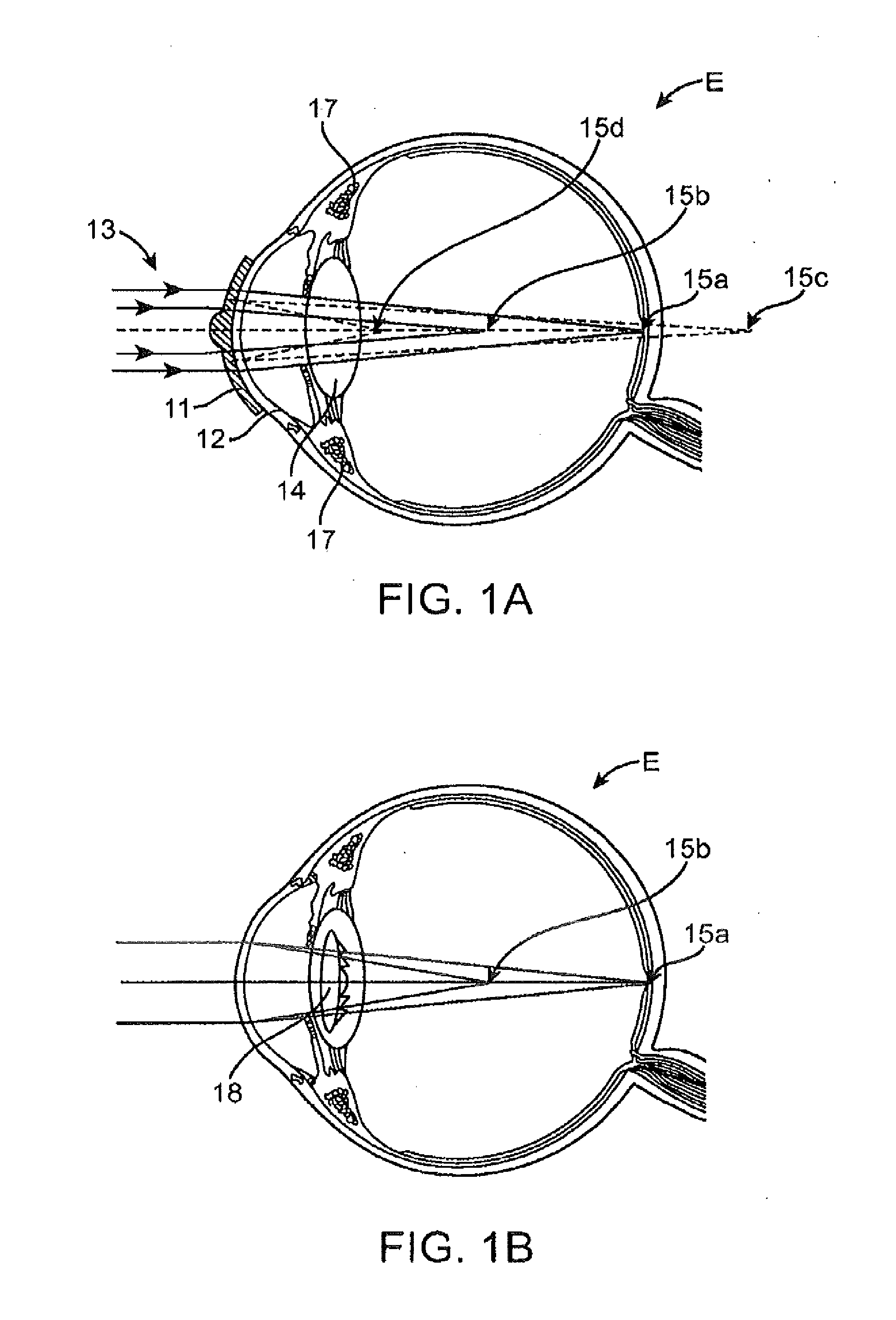
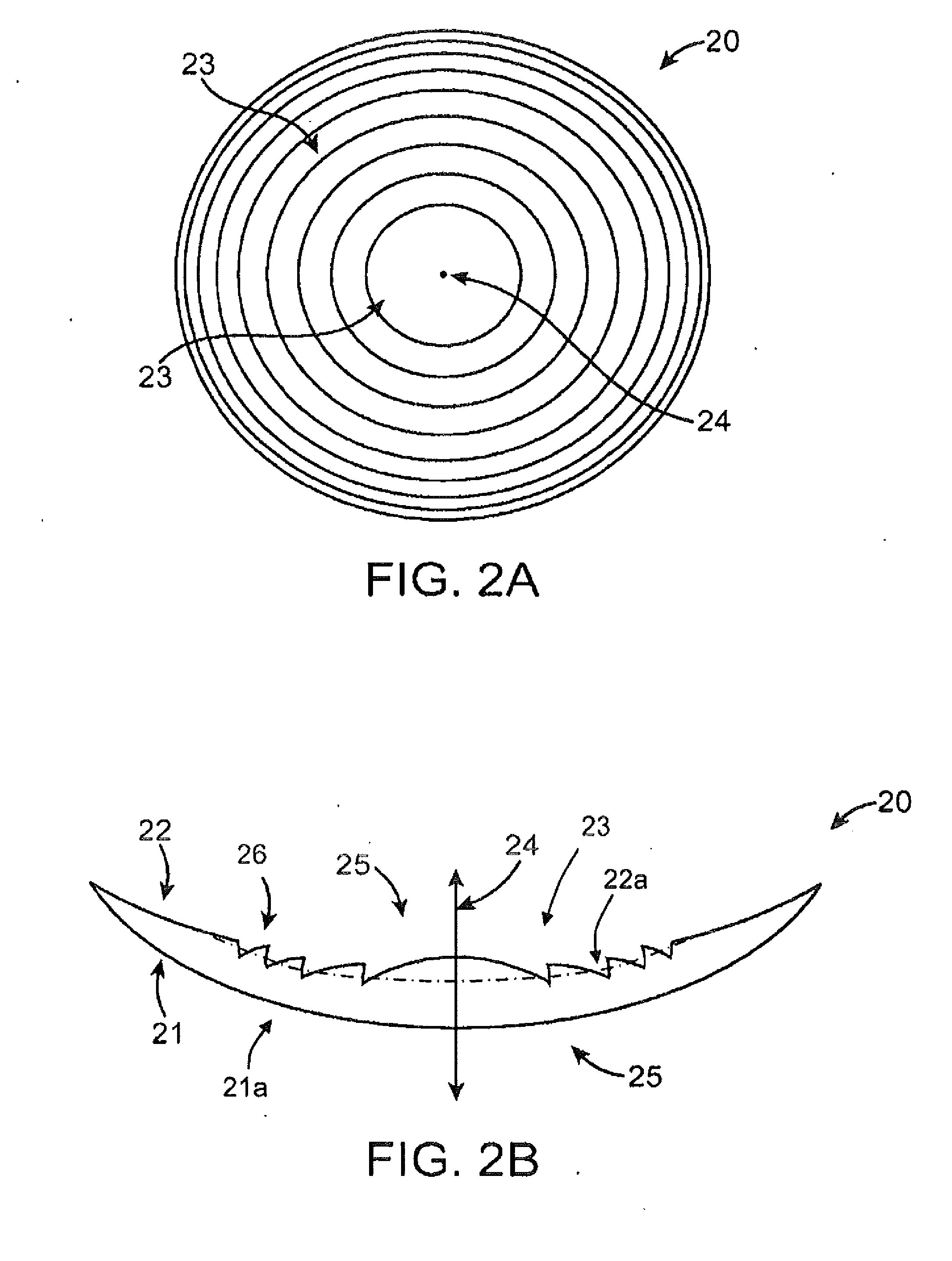
[0043]The present invention generally provides improved lenses and imaging systems. Embodiments of the invention may find their most immediate use may be in the form of improved ophthalmic devices, systems, and methods. Exemplary embodiments of the present invention provide improved ophthalmic lenses (including, for example contact lenses, intraocular lenses (IOLs), corneal lenses and the like) and associated methods for their design and use. Embodiments of the present invention include monofocal diffractive lenses, bifocal diffractive lenses, and multifocal diffractive lenses. Exemplary embodiments provide multifocal diffractive ophthalmic lenses having reduced light scatter and / or improved light energy distribution so as to enhance viewing performance, for example, through subtle shaping of a smoothly curving profile extending across a plurality of echelettes. The surface is generally optically smooth to help reduce scatter. As used herein, “optically smooth” means having an avera...


PUM


Abstract

Ophthalmic lenses and methods for their design and use involve displacement functions based on the sum of a continuous cosine function and a continuous sine function, optionally over a plurality of echelettes. Exemplary monofocal and multifocal diffractive ophthalmic lenses provide reduced light scatter and / or improved light energy distribution properties. Such properties can be provided by diffractive profiles, often having subtlety shaped echelettes with appropriately curving profiles. Light scatter may be generated by the sharp corners associated with vertical steps between adjacent conventional diffractive echelettes. Smooth diffractive profiles of the invention reduce light scatter. Light energy directed toward non-viewing diffractive orders may have a unwanted effects on vision quality. Diffractive profiles as described herein may limit the light energy in certain, selected orders, thereby improving viewing quality and mitigating unwanted effects such as dysphotopsia. Diffractive profiles may also vary the light energy distributed between individual echelettes, providing additional advantages in various viewing situations.

Description

CROSS-REFERENCES TO RELATED APPLICATIONS[0001]This application claims priority to U.S. Application No. 61 / 667,544, filed on Jul. 3, 2012. This application is related to U.S. Pat. No. 7,871,162, U.S. Patent Publication Nos. 2009 / 0268155 and 2011 / 0109875, and U.S. patent application Ser. No. 12 / 962,255 filed Dec. 7, 2010. The entire content of each of these filings is incorporated herein by reference for all purposes. Full Paris Convention priority is hereby expressly reserved.BACKGROUND OF THE INVENTION[0002]Embodiments of the present invention relate to ophthalmic lenses such as, for example, contact lenses or intraocular lenses (IOLs). Exemplary embodiments include monofocal and multifocal diffractive ophthalmic lenses having reduced light scatter and / or improved light energy distribution, for example, through subtle shaping of echelettes with appropriately curving profiles.[0003]Presbyopia is a condition that affects the accommodation properties of the eye. As objects move closer ...

Claims


Application Information

Patent Timeline
Patent Type & Authority Applications(United States)
IPC IPC(8): G02C7/02G02C7/06
CPCG02C7/022G02C7/06G02C7/024A61F2/1654G02C7/028G02C7/041G02C2202/20A61F2002/1699
Inventor ZHAO, HUAWEI
Owner JOHNSON & JOHNSON SURGICAL VISION INC
Why Eureka
Eureka Blog
Learn More