Rotary Cutting Tool and Reversible Cutting Insert Therefor

a cutting tool and insert technology, applied in the field of cutting inserts and cutting tools, can solve the problem of limited shoulder depth

Active Publication Date: 2014-01-09
ISCAR LTD
View PDF6 Cites 58 Cited by
  • Summary
  • Abstract
  • Description
  • Claims
  • Application Information

AI Technical Summary

Benefits of technology

[0012]In accordance with another aspect of the invention, there is provided a cutting tool rotatable about a tool axis, comprising a cutting body having an insert receiving pocket, and at least one reversible indexable cutting insert of the sort described above removably secured in the insert receiving pocket.

Problems solved by technology

However, the depth of the shoulder is limited by the size of the insert and dependent on the length of the primary cutting edge.

Method used


Image

  • Rotary Cutting Tool and Reversible Cutting Insert Therefor
  • Rotary Cutting Tool and Reversible Cutting Insert Therefor
  • Rotary Cutting Tool and Reversible Cutting Insert Therefor

Examples


Embodiment Construction

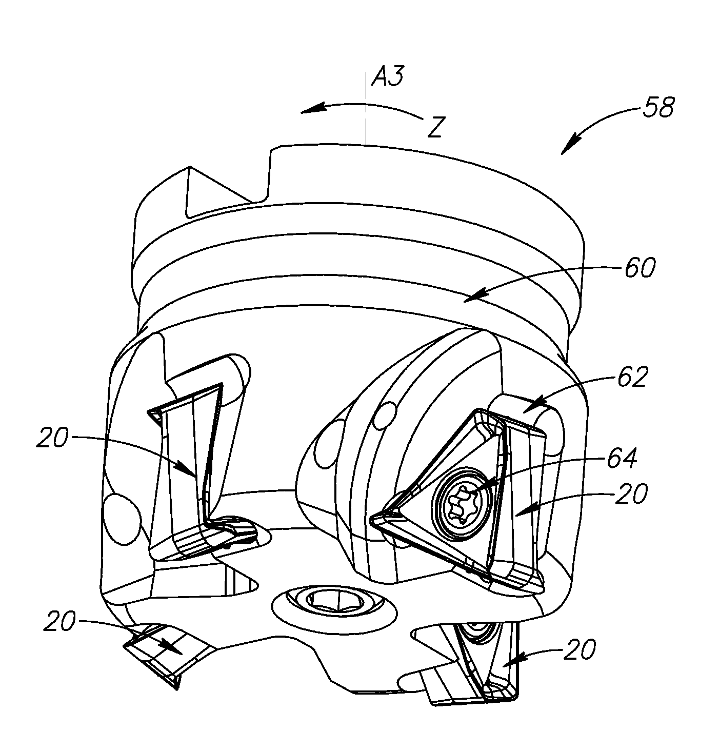
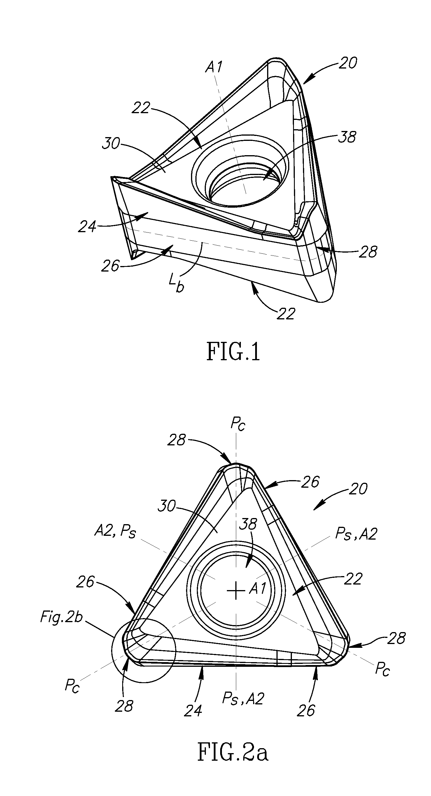
[0025]The present invention relates to a reversible indexable cutting insert 20 having opposing first and second end surfaces 22 interconnected by a continuous peripheral surface 24, the peripheral surface 24 at least three side surfaces 26 alternating with at least three corner surfaces 28.

[0026]In some embodiments of the present invention, the at least three side surfaces 26 may be identical, and the at least three corner surfaces 28 may be identical.

[0027]As shown in FIGS. 1 and 2a, the cutting insert 20 may have the basic shape of a regular polygon.

[0028]In some embodiments of the present invention, the cutting insert 20 may preferably be manufactured by form pressing and sintering a cemented carbide, such as tungsten carbide, and may be coated or uncoated.

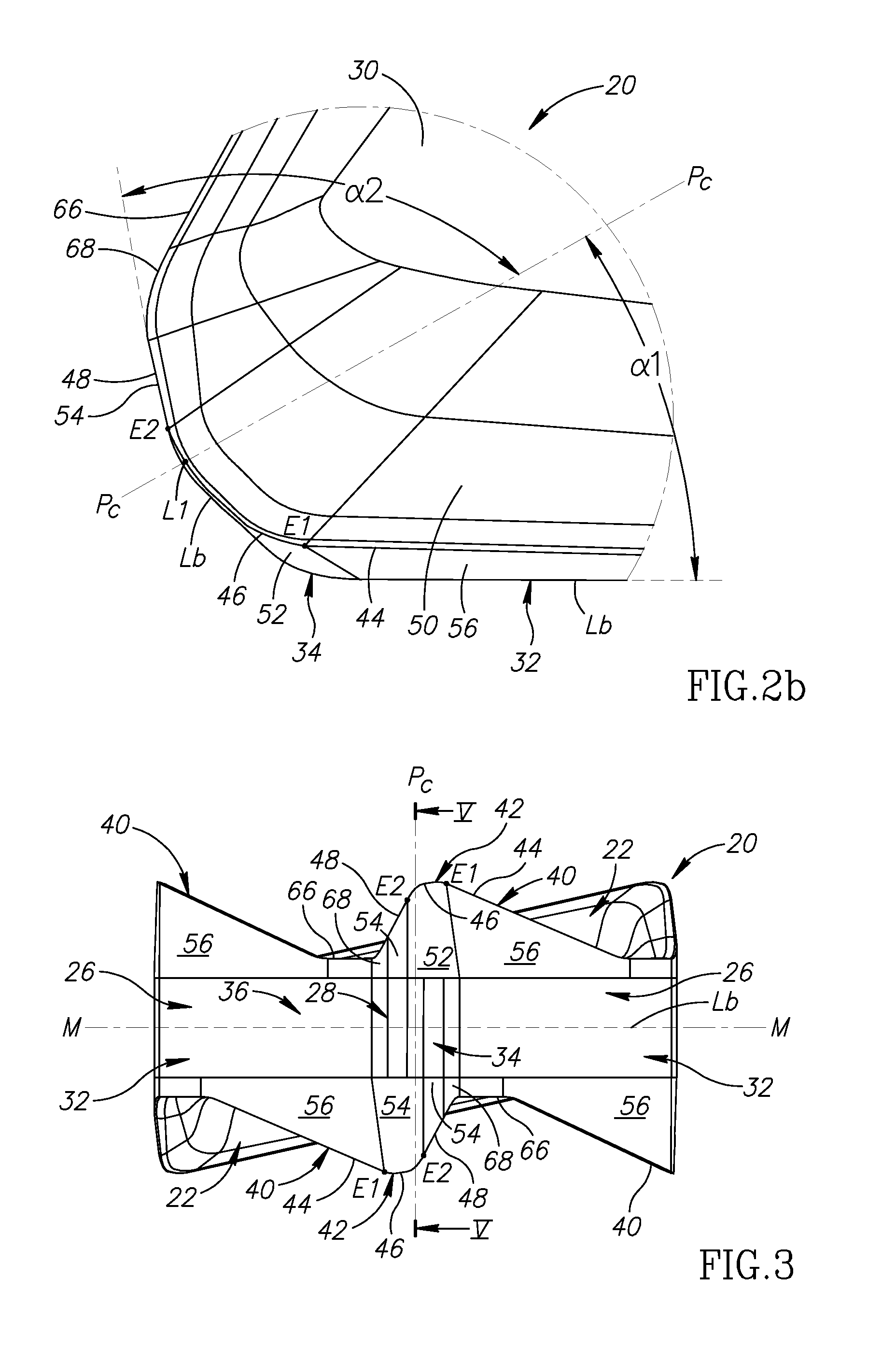
[0029]As shown in FIGS. 3 and 4, the cutting insert 20 has a median plane M located between the first and second end surfaces 22 and intersecting the peripheral surface 24 to form an insert boundary line Lb.

[0030]In some embod...


PUM

PropertyMeasurementUnit
bisector angleaaaaaaaaaa
corner cutting angleaaaaaaaaaa

Abstract

In a rotary cutting tool used for milling operations, a reversible indexable cutting insert is removably secured in a cutting body. The cutting insert has two opposing end surfaces interconnected by a continuous peripheral surface, including three side surfaces alternating with three corner surfaces. The side and corner surfaces intersect with both end surfaces at side and corner edges, respectively, with each side edge having a major cutting edge, and each corner edge having a corner and minor cutting edge. Each major and minor cutting edge slopes away from first and second end points, respectively, of its mutually associated corner cutting edge, towards a median plane. A first imaginary straight line extending perpendicular to the median plane and intersecting any one of the corner cutting edges at any point along its length except the second end point, passes through the median plane inside an insert boundary line.

Description

FIELD OF THE INVENTION[0001]The present invention relates to cutting inserts and cutting tools for use in metal cutting processes, in general, and to rotary cutting tools having reversible cutting inserts for milling operations, in particular.BACKGROUND OF THE INVENTION[0002]Within the field of rotary cutting tools used in milling operations, there are many examples of reversible cutting inserts being removably secured in a cutting body. In some instances, these cutting tools are configured to perform square shoulder milling operations.[0003]U.S. Pat. No. 7,241,082 discloses a generally rectangular shaped double-sided indexable cutting insert having two major and two minor side surfaces connected to two opposing end surfaces, and a total of four major cutting edges. A primary ‘reversed’ relief surface adjacent each major cutting edge is inclined to a median plane of the cutting insert at an acute interior angle. The cutting insert is retained in the insert pocket of a milling cutter...

Claims


Application Information

Patent Timeline
Patent Type & Authority Applications(United States)
IPC IPC(8): B23C5/20B23B27/16
CPCB23C2200/286B23C5/06B23B2200/3681B23C2200/123B23C2200/201B23C2200/208B23C2200/0477B23C5/202Y10T407/1924Y10T407/23B23B5/20
Inventor SMILOVICI, CAROLATAR, OSAMA
Owner ISCAR LTD
Why Eureka
Try Eureka