Nanoreinforced films and laminates for aerospace structures

a technology of nano-forced films and aerospace structures, which is applied in the direction of braiding, knitting, application, etc., can solve the problems of reducing the fuel economy of the aircraft on which these structures are used, requiring erosion resistance in the environment in which these structures operate, and high drag coefficients, so as to improve ultraviolet resistance and resistance to microcracking

Active Publication Date: 2014-01-09
ROHR INC +1
View PDF3 Cites 52 Cited by
  • Summary
  • Abstract
  • Description
  • Claims
  • Application Information

AI Technical Summary

Benefits of technology

[0006]A composite laminate for use on an external part of an aerospace vehicle has improved ultraviolet resistance and resistance to microcracking from thermal cycling. The laminate comprises a nanoreinforcement film, a support veil, and a composite layer. The laminate also can have a lightning strike protection layer and an external paint and primer. The nanoreinforcement film can comprise carbon nanomaterial and a polymer resin, and the composite layer has one or more layers of a reinforcement and a polymer resin. The carbon nanomaterial can be carbon nanofibers, and the nanoreinforcement film can have an areal weight of less than about 100 g / m2. The carbon nanomaterial can also comprise carbon nanofibers and carbon nanotubes.

Problems solved by technology

Second, the environment in which these structures operate also requires erosion resistance, as aerospace structures are exposed to impact by rain, sand, ice, hail and other foreign objects.
These objects can degrade surface finish and create abrasion, which can result in high drag coefficients, which contributes to reduced fuel economy for the aircraft on which they are used.
Third, the changes in altitude and temperature differentials during operation of an aircraft subject the aircraft's components to extreme thermal cycling that can cause microcracking.
Fourth, long term exposure to sunlight and ultraviolet (UV) radiation can degrade the properties of aircraft components.
For example, a newly designed film may provide superior erosion resistance but at the expense of degraded UV resistance and / or lightning strike protection.

Method used


Image

  • Nanoreinforced films and laminates for aerospace structures
  • Nanoreinforced films and laminates for aerospace structures
  • Nanoreinforced films and laminates for aerospace structures

Examples


Embodiment Construction

[0011]Certain exemplary embodiments of the present invention are described below and illustrated in the accompanying figures. The embodiments described are only for purposes of illustrating the present invention and should not be interpreted as limiting the scope of the invention. Other embodiments of the invention, and certain modifications and improvements of the described embodiments, will occur to those skilled in the art and all such alternate embodiments, modifications, and improvements are within the scope of the present invention.

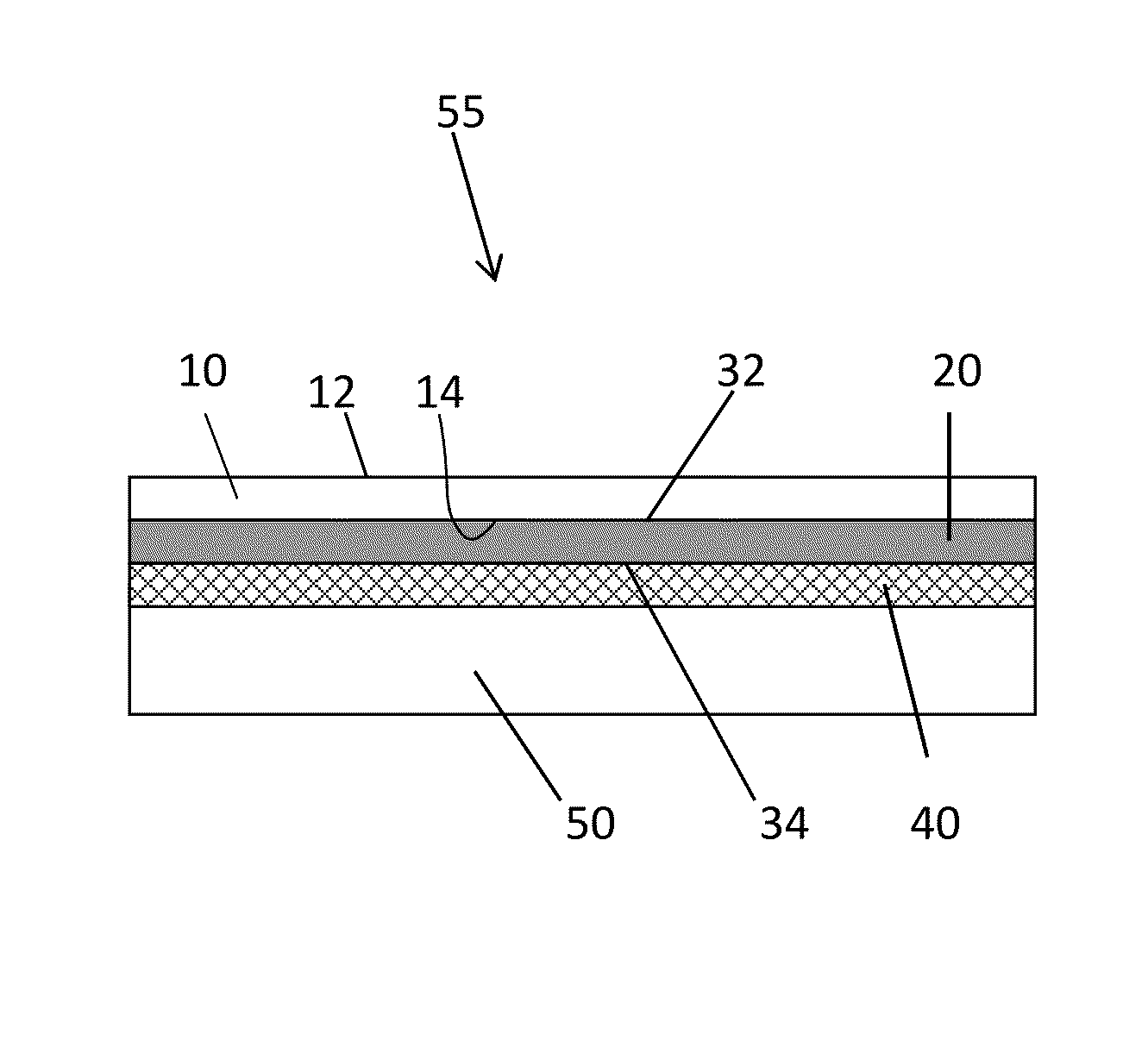
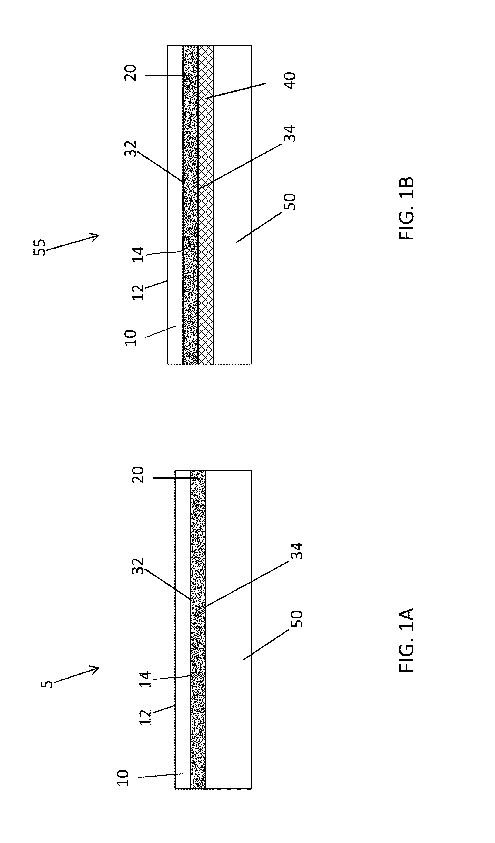
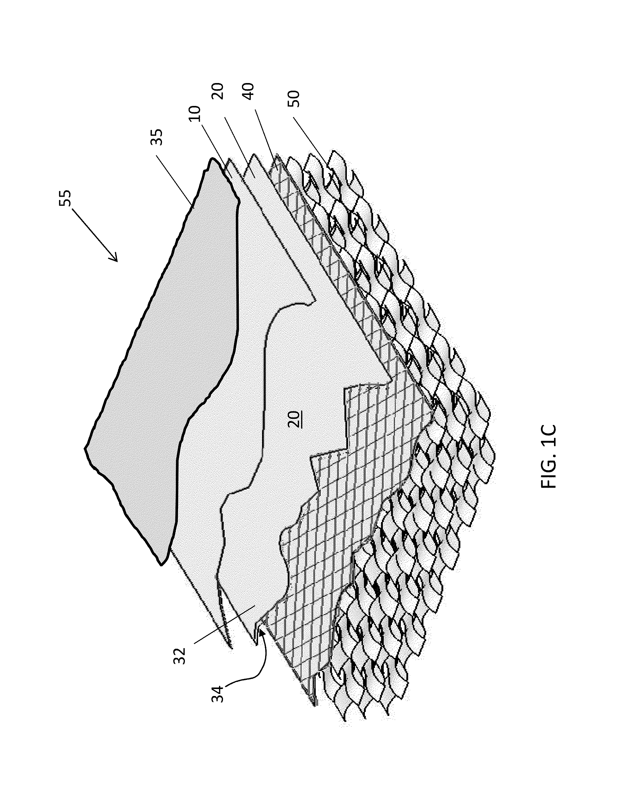
[0012]FIG. 1A shows a composite laminate 5. This figure shows a laminate lay-up construction or assembly of one embodiment. Laminate 5 includes a layer of a nanoreinforced film 10, a support veil 20, and a composite layer 50. FIG. 1B shows a composite laminate 55 according to another embodiment of this invention. FIG. 1B shows a laminate lay-up construction or assembly, and includes an optional lightning strike layer 40. FIG. 1C shows a perspective,...


PUM

PropertyMeasurementUnit
lengthaaaaaaaaaa
diameteraaaaaaaaaa
lengthaaaaaaaaaa

Abstract

A composite laminate for use on an external part of an aerospace vehicle has improved ultraviolet resistance and resistance to microcracking from thermal cycling. The laminate comprises a nanoreinforcement film, a support veil, and a composite layer. The laminate also can have a lightning strike protection layer and an external paint and primer. The nanoreinforcement film can comprise carbon nanomaterial and a polymer resin, and the composite layer has one or more layers of a reinforcement and a polymer resin. The carbon nanomaterial can be carbon nanofibers, and the nanoreinforcement film can have an areal weight of less than about 100 g / m2. The carbon nanomaterial can also comprise carbon nanofibers and carbon nanotubes.

Description

FIELD OF THE INVENTION[0001]The present invention relates to surface films and laminates for use in aerospace structures, and in particular to nanoreinforced films and laminates for aerospace structures with enhanced properties.BACKGROUND OF THE INVENTION[0002]Aerospace designers must balance several factors in the design of structures and components. Designers appreciate the complex interplay between weight, strength, costs, material properties, environmental conditions and the multitude of service requirements for various components. First, aircraft components must be lightweight to ensure fuel economy, but strong enough to meet structural and performance requirements. Hence, composite structures often are selected due to their sturdiness and low weight densities. Second, the environment in which these structures operate also requires erosion resistance, as aerospace structures are exposed to impact by rain, sand, ice, hail and other foreign objects. These objects can degrade surf...

Claims


Application Information

Patent Timeline
Patent Type & Authority Applications(United States)
IPC IPC(8): B32B27/18B32B17/04D04C1/00B32B27/12B32B15/04B82Y30/00
CPCB32B5/16B32B5/24B32B2260/023B32B2307/20B32B2307/71B32B2605/18B64C3/20B64C2001/0072B64C2027/4736B64D45/02Y02T50/40Y10T428/249921Y10T428/273Y10T442/30Y10T442/40Y10T442/60
Inventor KRUCKENBERG, TERESA MAYPUJAR, VIJAY V.MAZANY, ANTHONY M.
Owner ROHR INC
Why Eureka
Try Eureka