Transmission unit

a transmission unit and axial direction technology, applied in the direction of gearing control, gearing elements, belts/chains/gearings, etc., can solve the problems of reducing the installation space of the transmission unit in the axial direction, reducing the stability and/or robustness of the electric motor, etc., to achieve the effect of simple assembly and reduced weigh

Inactive Publication Date: 2014-01-16
BROSE FAHRZEUGTEILE GMBH & CO KG HALLSTADT (DE)
View PDF15 Cites 0 Cited by
  • Summary
  • Abstract
  • Description
  • Claims
  • Application Information

AI Technical Summary

Benefits of technology

The present invention aims to provide a lightweight and easy-to-assemble transmission unit and electric motor for use in various applications. The technical effect is to offer a simplified and lightweight solution for transmitting power.

Problems solved by technology

The reduced stability and / or robustness of the electric motor caused by the absence of an A-side bearing is compensated for by the positioning of the stator inside the transmission housing, which also reduces the installation space of the transmission unit in the axial direction.

Method used


Image

  • Transmission unit
  • Transmission unit
  • Transmission unit

Examples


Embodiment Construction

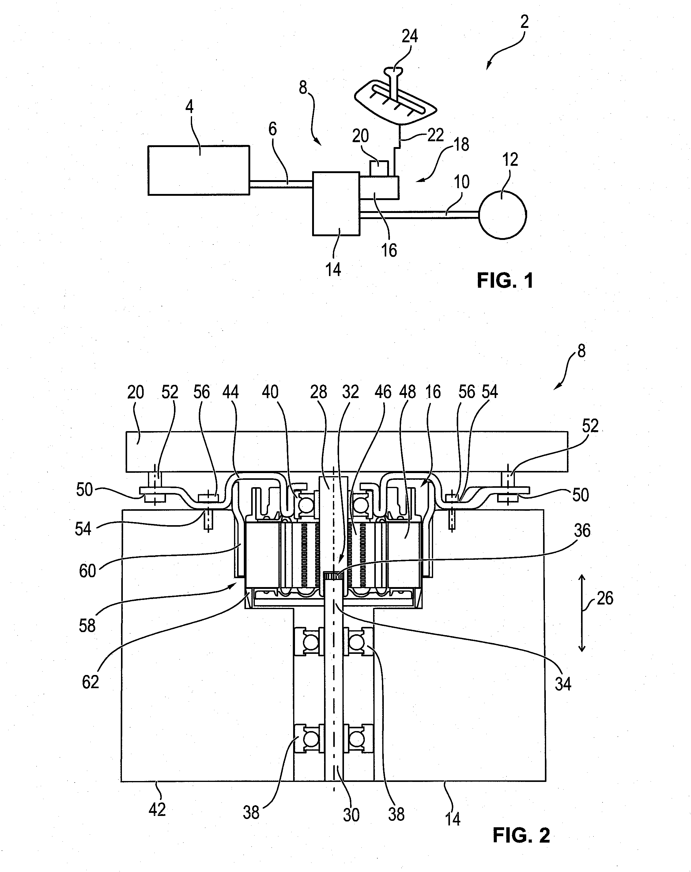
[0027]In FIG. 1 a simplified schematic view of a drive train 2 of a motor vehicle is shown. An internal combustion engine 4 stands in operative connection with drive wheels 12 through a first shaft 6, a transmission unit 8, a second shaft 10, and a differential that is not shown. In this arrangement, the rotational motion of the first shaft 6, which is driven directly by the internal combustion engine 4, is converted into a rotational motion of the drive wheels 12, with both the direction of rotation and the rotational speeds of the two being different. Because of the differential, the rotational motion of the drive wheels 12 takes place essentially at a right angle to the rotational motion of the second shaft 10.

[0028]By means of a transmission 14 of the transmission unit 8, a torque provided by the internal combustion engine 4 is transmitted variably to the drive wheels 12. For this purpose, the transmission 14 has a clutch that is operated by means of a transmission actuator 18 t...


PUM


Abstract

A transmission unit of a motor vehicle, with a transmission having a transmission shaft and with an electric motor that is coupled thereto in an axial direction and that has a stator and that has a rotor arranged on a motor shaft and that is bearingless on the A-side. The electric motor includes an end plate on the B-side, and the stator is located at least partly inside a housing of the transmission.

Description

[0001]This nonprovisional application claims priority under 35 U.S.C. §119(a) to German Patent Application No. DE 10 2012 013 947.0, which was filed in Germany on Jul. 12, 2012, and which is herein incorporated by reference.BACKGROUND OF THE INVENTION[0002]1. Field of the Invention[0003]The present invention relates to a transmission unit of a motor vehicle, with a transmission and with an electric motor coupled thereto in the axial direction. The invention also concerns such an electric motor.[0004]2. Description of the Background Art[0005]In at least partly automatic transmissions of motor vehicles, the individual shift stages (gears) are set by means of a transmission actuator. For this purpose, the transmission actuator has a so-called selector finger and an electric motor, wherein the selector finger can be moved by the electric motor, and wherein the position of the selector finger determines the desired transmission ratio.[0006]A brushless electric motor whose stator is suppl...

Claims


Application Information

Patent Timeline
Patent Type & Authority Applications(United States)
IPC IPC(8): F16H61/26
CPCF16H61/26F16H2057/02034F16H61/32F16H57/02Y10T74/19251
Inventor BAUMGARTNER, JOACHIMFUELLER, DOMINIKOTTO, CHRISTOPHPONDELEK, MARTIN
Owner BROSE FAHRZEUGTEILE GMBH & CO KG HALLSTADT (DE)
Why Eureka
Try Eureka