
Back lighted membrane keyboard with parts being secured together by subjecting to ultrasonic welding

a membrane keyboard and backlight technology, applied in the field of membrane keyboards, can solve the problems of affecting the yield of the product, the parts of the u.s. patent are not always aligned, and the limited operation of most types of laptops

Inactive Publication Date: 2014-01-16
SUNREX TECH
View PDF9 Cites 13 Cited by
  • Summary
  • Abstract
  • Description
  • Claims
  • Application Information

AI Technical Summary

Benefits of technology

The patent describes a membrane keyboard with transparent keys that have a key shaft and a plastic housing with rectangular openings and stems. There is also a membrane circuit board with elastic members and a light blocking layer. The keyboard also includes scissor-shaped structures with slide axles and pivot shafts that are secured to the keys. A transparent light emitting and guiding plate is connected to the membrane circuit board and has openings aligned with the keys. An aluminum plate with retaining members and bosses is positioned below the light emitting and guiding plate and the stems are fastened to the retaining members using ultrasonic welding. The technical effect of this invention is to provide a membrane keyboard with transparent keys and a simplified and reliable method of making it.

Problems solved by technology

However, most types of laptops are limited to operate in a bright environment since there is no backlight device provided.
While the U.S. Patent has been successfully used in a commercial application, in practice it is found that parts of the U.S. Patent are not always aligned since they are assembled by adhesive.
This adversely lowers the yield.

Method used


Image

  • Back lighted membrane keyboard with parts being secured together by subjecting to ultrasonic welding
  • Back lighted membrane keyboard with parts being secured together by subjecting to ultrasonic welding
  • Back lighted membrane keyboard with parts being secured together by subjecting to ultrasonic welding

Examples


Embodiment Construction

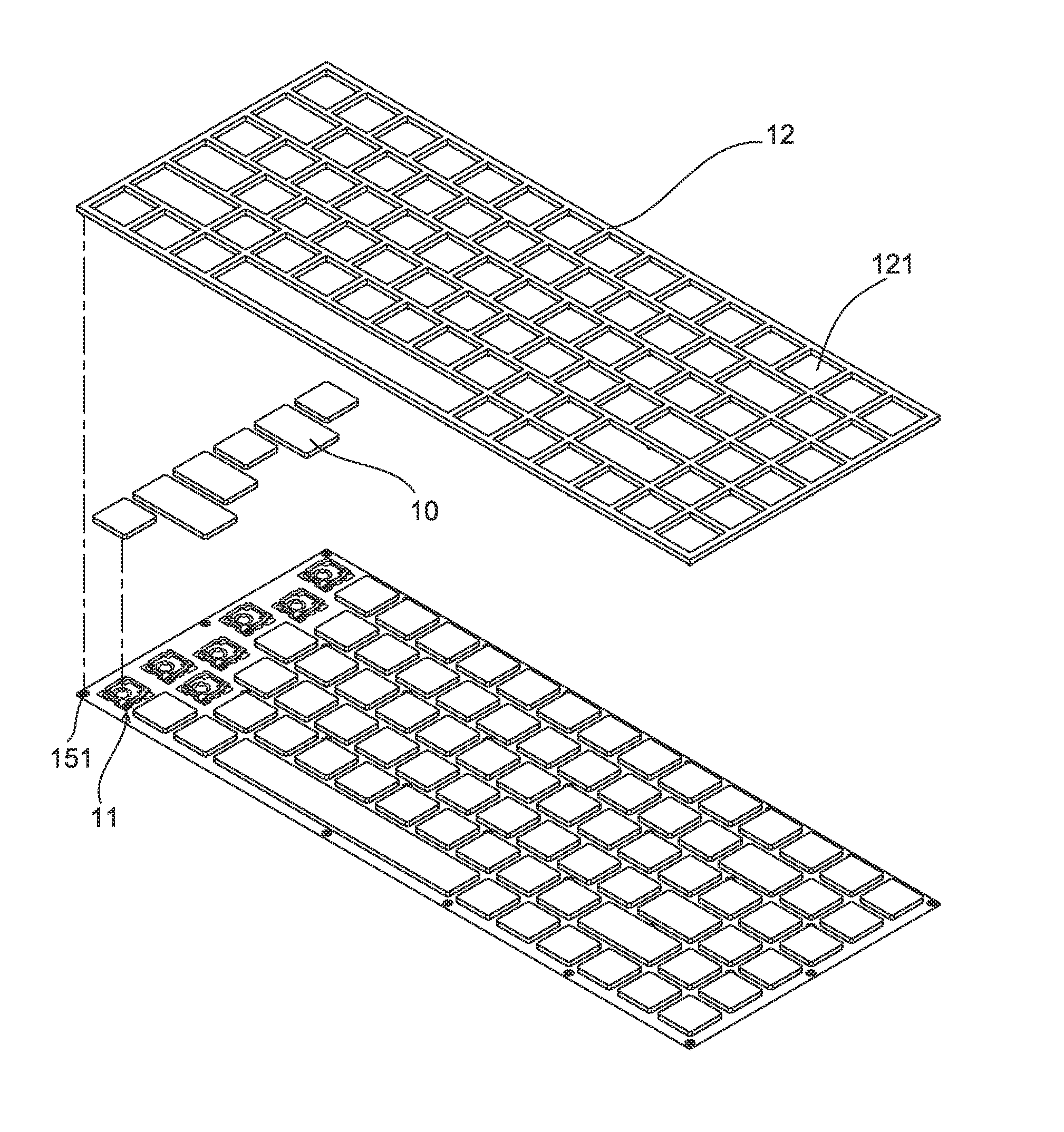
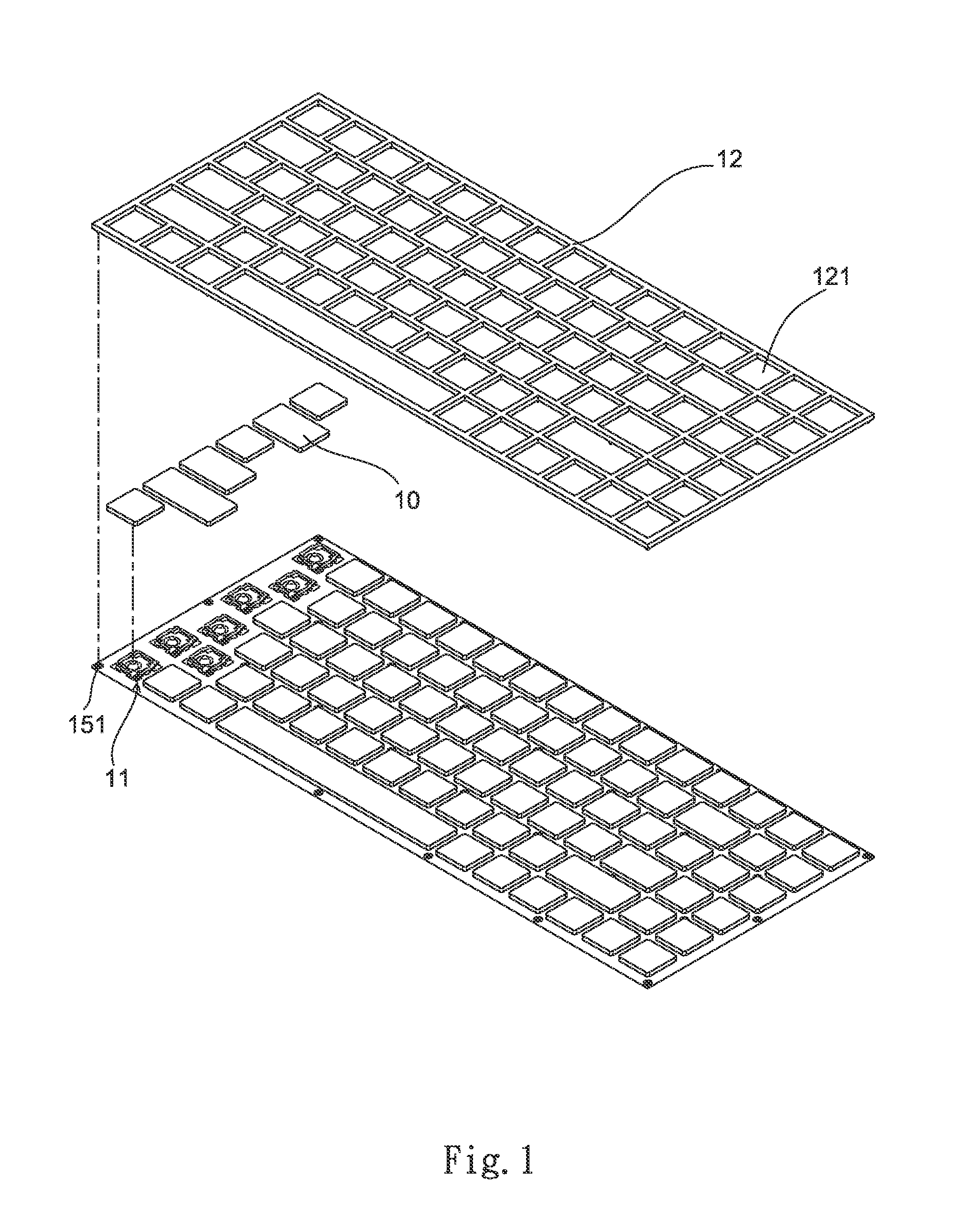
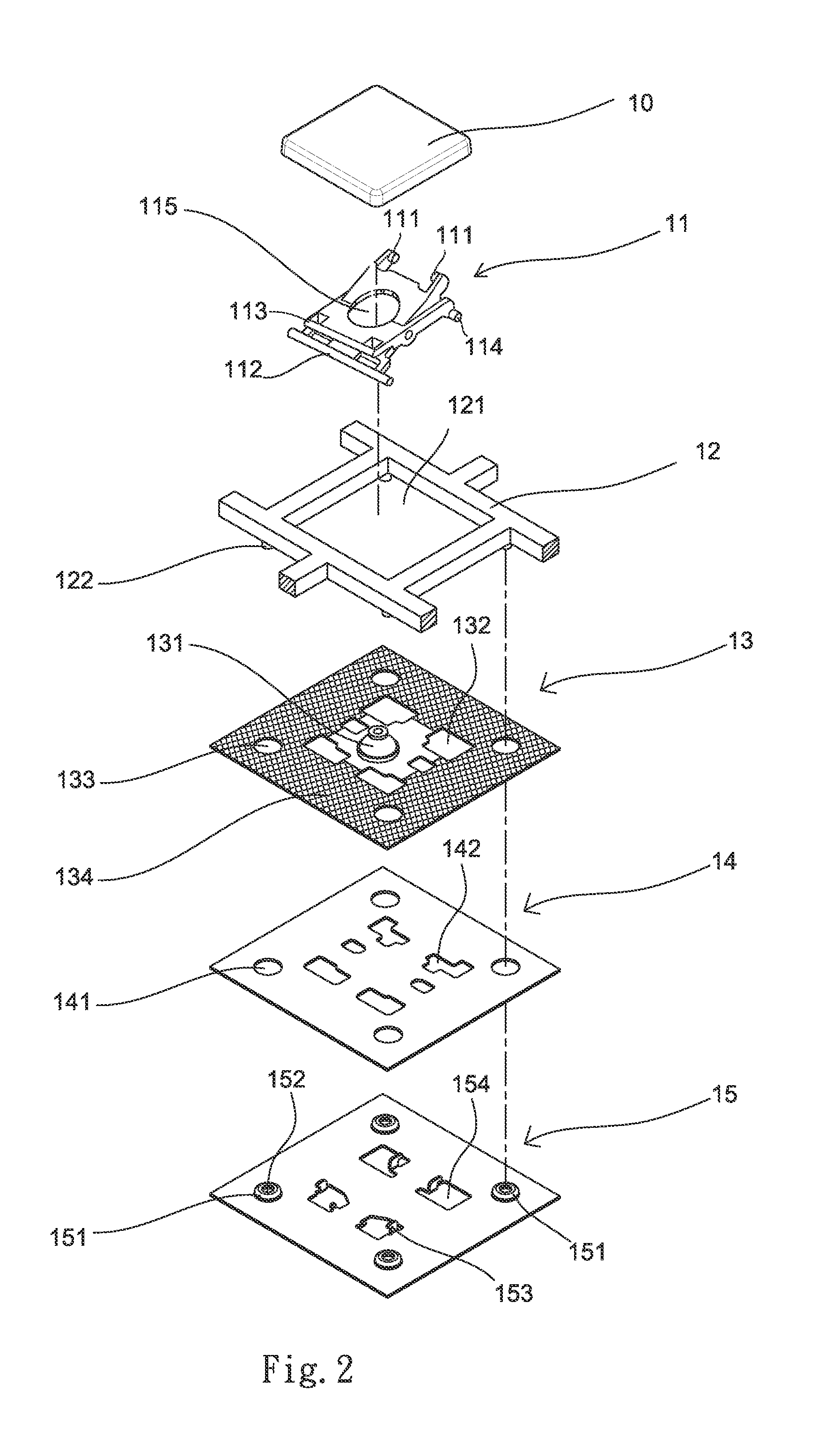
[0013]Referring to FIGS. 1 to 4, a membrane keyboard according to a preferred embodiment of the invention is shown. The membrane keyboard is for laptop and comprises the following components, substantially from top to bottom, as discussed in detail below.

[0014]A plurality of transparent keys 10 each has a rectangular top surface. On the bottom of the key 10 there are provided a central key shaft 101 extending downward and two pairs of retaining structures (not numbered).

[0015]A substantially rectangular key housing 12 is made of plastics and comprises a plurality of rectangular openings 121 with the key 10 disposed therein, and a plurality of downward extending stems 122.

[0016]A membrane circuit board 13 is disposed below the key housing 12 and comprises circuitry, a plurality of dome-shaped elastic members 131 formed of a flexible insulative material (e.g., elastomeric material), the elastic member 131 including a central top receptacle (not numbered) for the receipt of the key sha...


PUM


Abstract

A membrane keyboard is provided with transparent keys each including a bottom key shaft; a key housing including openings for receiving the keys, and downward extending stems; a membrane circuit board below the key housing and including elastic members and a light blocking layer; scissor-shaped structures each including a central opening, two first slide axles, two second slide axles below the first slide axles, a first pivot shaft opposing the first slide axles, and a second pivot shaft opposing the second slide axles and below the first pivot shaft wherein the first slide axles and the first pivot shaft are pivotably secured to the key bottom; a transparent light emitting and guiding plate below and electrically connected to the membrane circuit board; and an aluminum plate below the light emitting and guiding plate and including retaining members for pivotably receiving the second slide axles and the second pivot shaft.

Description

BACKGROUND OF THE INVENTION[0001]1. Field of the Invention[0002]The invention relates to membrane keyboards and more particularly to a back lighted membrane keyboard having parts being secured together by subjecting to ultrasonic welding.[0003]2. Description of Related Art[0004]Laptops are widely used by people throughout the world due to portability, word processing, and other capabilities common to desktop computers, and Internet access. Membrane keyboards are typically incorporated into laptops. Membrane keyboards are advantageous for being thin, lightweight, and compact. However, most types of laptops are limited to operate in a bright environment since there is no backlight device provided.[0005]For overcoming above drawback, in my earlier U.S. Pat. No. 7,608,792, an improved membrane keyboard / keypad with arrangement for uniformly lighting keys from background is disclosed.[0006]While the U.S. Patent has been successfully used in a commercial application, in practice it is foun...

Claims


Application Information

Patent Timeline
IPC IPC(8): H01H13/76
CPCH01H3/125H01H13/702H01H13/88H01H2211/006H01H2215/004H01H2219/014H01H2219/036H01H2219/062H01H2223/034H01H2229/036
Inventor TSAI, HUO-LU
Owner SUNREX TECH
Learn More