Real-time detection and weld quality prediction in vibration welding process

A vibration welding and quality technology, applied in welding equipment, non-electric welding equipment, structural parts, etc., can solve problems such as difficulty in producing consistent high-quality welding parts, welding parts affecting the performance of the welded system, and affecting welding quality

Inactive Publication Date: 2013-05-01
GM GLOBAL TECH OPERATIONS LLC
View PDF8 Cites 43 Cited by
  • Summary
  • Abstract
  • Description
  • Claims
  • Application Information

AI Technical Summary

Problems solved by technology

However, stable welding process parameters still make it difficult to produce consistently high quality welds
In addition, external factors such as material quality can also affect welding quality
Also, premature failure of a weld can affect the performance of the welded system

Method used


Image

  • Real-time detection and weld quality prediction in vibration welding process
  • Real-time detection and weld quality prediction in vibration welding process
  • Real-time detection and weld quality prediction in vibration welding process

Examples


Embodiment Construction

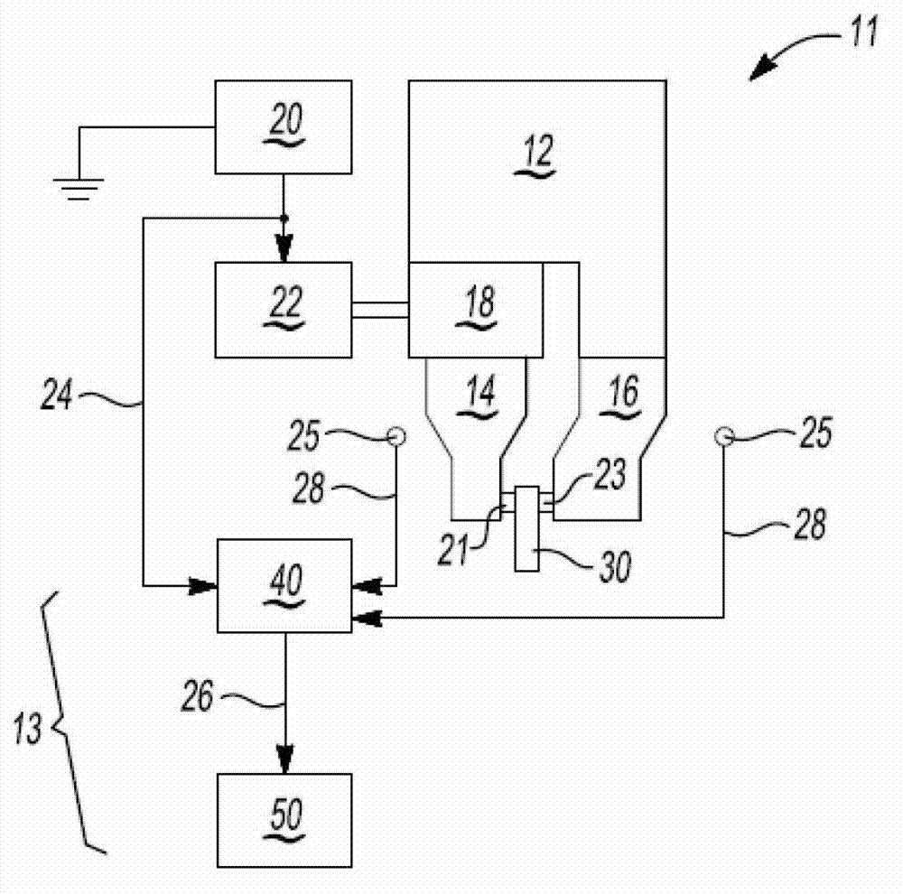
[0014] Referring to the drawings, in which like reference numerals indicate like parts in the several views, a vibration welding system 11 is schematically shown in figure 1 middle. The vibration welding system 11 includes a welding assembly 12 and a monitoring system 13 . Monitoring system 13 is in communication with welding assembly 12 . The purpose of using the monitoring system 13 is to improve production efficiency by substantially eliminating spurious conditions during the vibration welding process and by reducing direct manual or spot checks of each weld in a completed assembly.

[0015] figure 1 The illustrated welding assembly 12 includes a sonotrode / horn 4 and an anvil 16, as well as other tools and components as described below. Monitoring system 13 is configured to monitor various control signals provided by power supply / welding controller 20 and / or measured by a set of sensors 25 positioned relative to welding apparatus 12 . The monitoring system 13 predicts o...


PUM


Abstract

A system includes a host machine and a status projector. The host machine is in electrical communication with a collection of sensors and with a welding controller that generates control signals for controlling the welding horn. The host machine is configured to execute a method to thereby process the sensory and control signals, as well as predict a quality status of a weld that is formed using the welding horn, including identifying any suspect welds. The host machine then activates the status projector to illuminate the suspect welds. This may occur directly on the welds using a laser projector, or on a surface of the work piece in proximity to the welds. The system and method may be used in the ultrasonic welding of battery tabs of a multi-cell battery pack in a particular embodiment. The welding horn and welding controller may also be part of the system.

Description

technical field [0001] The present invention relates to displaying welding quality status during vibration welding. Background technique [0002] The vibration welding process involves the controlled application of high frequency vibrational energy to a clamped workpiece. Surface friction is created at the weld interface, which eventually softens and bonds adjacent workpiece surfaces at the interface. The efficiency, consistency and long-term reliability / durability of vibration welded assemblies depends primarily on the welding tools and control methods used to form the various welds. [0003] Various closed-loop parameter based control techniques are commonly applied during the vibration welding process to maintain certain welding parameters within calibrated limits. This method can produce fairly consistent welding parameters over time. However, stable welding process parameters still make it difficult to produce consistently high quality welds. In addition, external f...

Claims


Application Information

Patent Timeline
Patent Type & Authority Applications(China)
IPC IPC(8): B23K20/10B23K20/26H01M50/536
CPCG01V8/12B23K20/10B23K31/125Y02E60/10H01M50/536
Inventor J.P.斯派塞J.A.埃布尔M.A.温西克D.查克拉博蒂J.布雷塞H.王P.W.塔沃拉J.S.戴维斯D.C.哈钦森R.L.里尔登S.乌特兹
Owner GM GLOBAL TECH OPERATIONS LLC
Why Eureka
Try Eureka