Gas impermeable tube joint and method of forming same

a technology of impermeable tube joints and gas, which is applied in the direction of hose connections, other domestic objects, mechanical instruments, etc., can solve the problems of gas infiltration and exfiltration, the amount of fuel vapor that may escape, and the danger to the environment of fuel vapor escape from the fuel fill system

Inactive Publication Date: 2005-06-16
FLUID ROUTING SOLUTIONS
View PDF23 Cites 41 Cited by
  • Summary
  • Abstract
  • Description
  • Claims
  • Application Information

AI Technical Summary

Problems solved by technology

The escape of fuel vapor from fuel fill systems can be hazardous to the environment, and as a result, the U.S. Environmental Protection Agency prescribes limits to the amount of fuel vapor that may escape from the filler pipe.
A significant problem with such hoses is that they are subject to gas infiltration and exfiltration.
Oxygen is particularly troublesome because it is able to penetrate all known plastic films, at least to some small degree.
Once oxygen has gained entry to such a heating system, it deteriorates the hoses and corrodes the pumping system.
Problematically, this method may allow for the permeation of gas through the joint connection.
If the tube has a metallic layer, the permeation may be worse because of the relative inflexibility of the tube material and the resulting inability of the tube to form a tight fit with the projection.

Method used


Image

  • Gas impermeable tube joint and method of forming same
  • Gas impermeable tube joint and method of forming same
  • Gas impermeable tube joint and method of forming same

Examples


Embodiment Construction

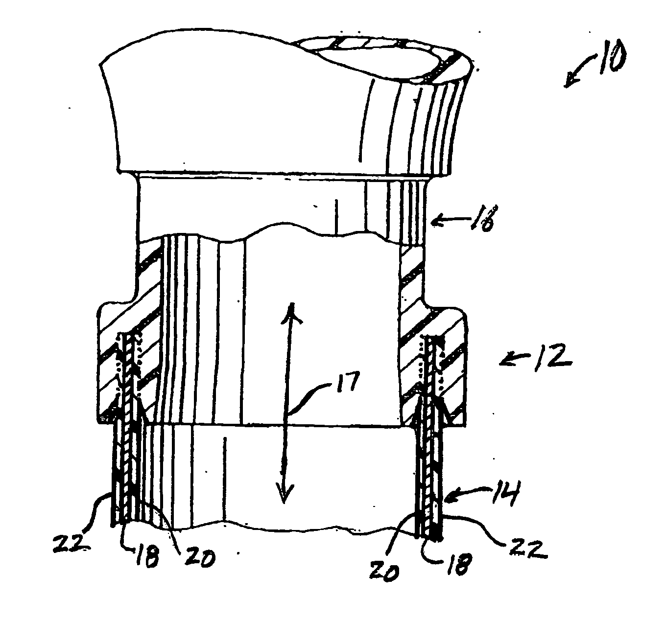
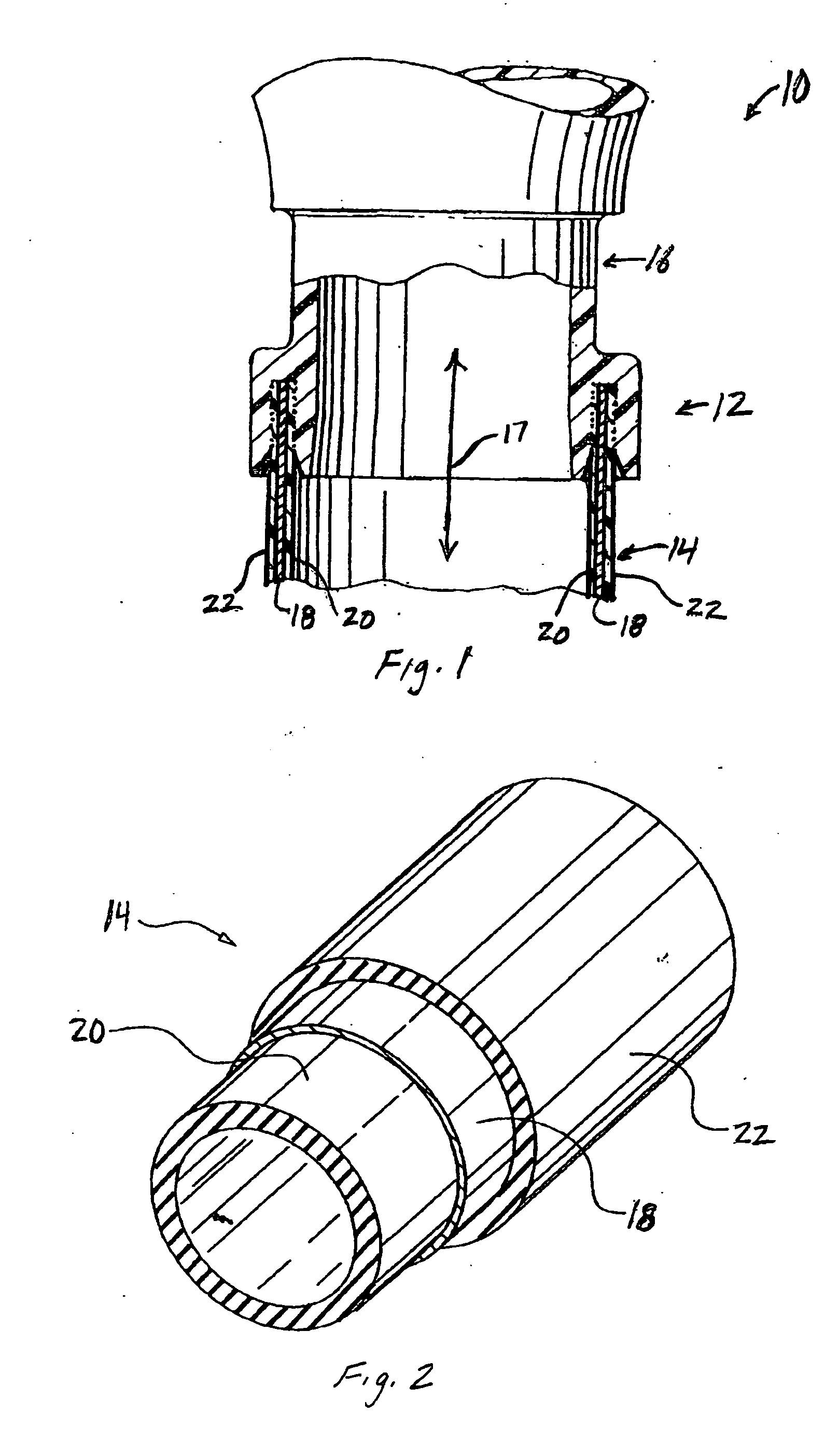
[0029]FIG. 1 is a partial cross-sectional view of a portion of a fluid system 10 including a gas impermeable tube joint 12. The fluid system 10 includes a tube 14 having an end coupled to a component 16 via the joint 12, which allows fluid to be communicated between the tube 14 and the component 16 as indicated by arrow 17. The component 16 may be any component in the fluid system 10 such as, for example a pump, funnel, tank, heat exchanger, valve, tube-to-tube coupling, flange, quick disconnect coupling, filter, and the like. For example, component 16 may be a funnel used within a fuel fill system in a motor vehicle, as described in commonly owned U.S. patent application Ser. No. ______ to Swane (Attorney Docket No. 02-13), filed concurrently herewith and entitled “Fuel Fill System”, which is incorporated by reference herein in its entirety. The component 16 may also be another tube. It will be appreciated that the fluid system 10 may include any number of joints 12 connecting tube...


PUM

PropertyMeasurementUnit
thicknessaaaaaaaaaa
thicknessaaaaaaaaaa
thicknessaaaaaaaaaa

Abstract

A method of forming a gas impermeable joint in a fluid system includes: providing a tube having a metallic barrier layer disposed between an inner plastic layer and an outer plastic layer; forcing at least one of the inner plastic layer and the outer plastic layer into contact with a plastic surface of a component; and welding the at least one of the inner plastic layer and the outer plastic layer with the plastic surface to form the gas impermeable joint. The welding may include: spin welding, hot plate welding, vibration welding, and ultrasonic welding. The metallic barrier layer extends substantially to the component, thus improving the gas impermeability of the joint between the tube and the component.

Description

BACKGROUND [0001] This invention relates to the joining of tubes to other components in fluid systems. More specifically, this invention relates to gas impermeable tube joints and methods for forming gas impermeable tube joints in fluid systems. [0002] In general, fluid systems serve to contain a fluid (e.g., a liquid, vapor, gas) as it is transported from one location to another. Fluid systems typically include a number of components interconnected by one or more tubes, which transport the fluid between the components. The components and tubes are connected together by joints, which allow the fluid to flow between the components and tubes while preventing leakage of the fluid from the system. [0003] For certain fluid systems, it is important to prevent the infiltration or escape of the fluid in its gaseous state. One such fluid system, for example, is a fuel fill system in a motor vehicle, through which fuel is delivered to a storage tank. The escape of fuel vapor from fuel fill sy...

Claims


Application Information

Patent Timeline
Patent Type & Authority Applications(United States)
IPC IPC(8): B29C65/00B29C65/02B29C65/06B29C65/08B29C65/20F16L13/02F16L13/14F16L47/02
CPCB29C65/02B29C66/723B29C65/0627B29C65/0672B29C65/08B29C65/20B29C66/1142B29C66/12441B29C66/5221B29C66/636B29L2009/003B29L2023/22F16L13/0254F16L47/02B29C65/06B29C66/1312B29C66/12463B29C65/00B29C66/8322B29C66/7392B29C66/71B29C65/7829B29C66/1222B29C66/1224B29C66/1226B29C66/12449B29C66/12469B29C66/1282B29C66/12841B29C66/322B29C66/7234B29C66/72321B29C66/73116B29K2077/00B29K2023/04B29K2023/10B29K2059/00B29K2027/12B29K2023/12B29K2023/06B29K2021/00
Inventor MOBLEY, JOHN E.THURSTON, MICHAEL O.SMITH, CHRISTOPHER W.
Owner FLUID ROUTING SOLUTIONS
Why Eureka
Try Eureka