
Method of anodizing hollow metallic bodies

Inactive Publication Date: 2014-01-16
THOMAS SA
View PDF4 Cites 4 Cited by
  • Summary
  • Abstract
  • Description
  • Claims
  • Application Information

AI Technical Summary

Benefits of technology

The patent is for an improved method of anodizing hollow metallic bodies. The new method solves problems of previous methods, such as slow treatment times and low quality surfaces. The new method produces high-quality anodized workpieces that are finished and in particular colored.

Problems solved by technology

The different dwell time in the anodizing bath and in a downstream coloring bath has a negative effect on the quality of the workpiece surfaces.
Moreover, the orientation of the workpieces results in quality differences between the anodized surfaces on the upper region and lower region of the hollow body.
Another disadvantage of the known method is that after pulling the vertically oriented workpiece holder out of the treatment bath, the treatment liquid does not completely flow off the workpieces within the limited time determined by the work cycle.
This results in significant carryover losses of the treatment liquid during movement of the workpiece holder from bath to bath.
This has a negative effect, among other things, on the sewage disposal and the consumption of chemicals.
It is difficult to set a very short treatment time and to combine it with baths that require a very long dwell time.
If the drum needs a plurality of revolutions for setting a long dwell time, it is also disadvantageous that during the treatment in the treatment liquid, the workpieces leave the treatment liquid again and again and dip again into the treatment liquid.
The method-related limitations have a negative effect on the surface quality of the workpieces.
In this method too, a significant carryover of the treatment liquid from treatment bath to treatment bath is unavoidable.

Method used


Image

  • Method of anodizing hollow metallic bodies
  • Method of anodizing hollow metallic bodies
  • Method of anodizing hollow metallic bodies

Examples


Embodiment Construction

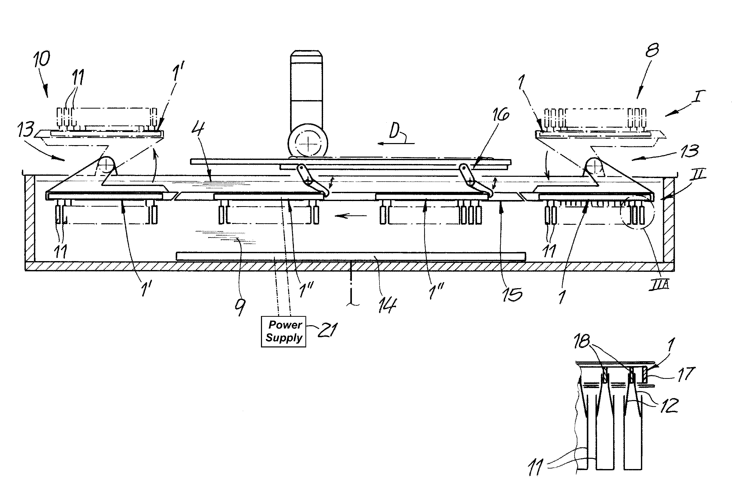
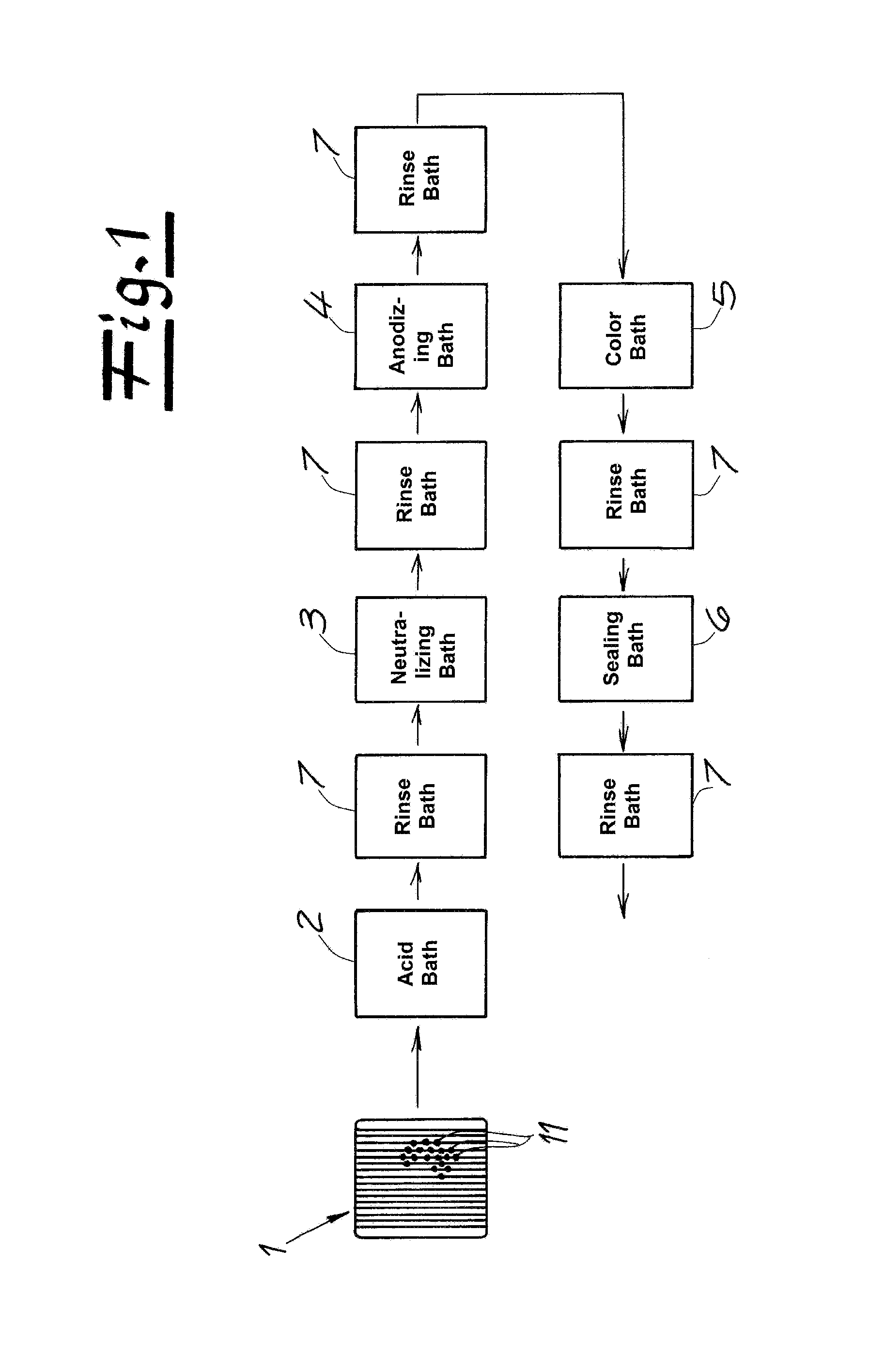
[0031]As seen in FIG. 1 hollow cup-shaped workpieces 11 (FIGS. 2-4) are secured on projecting fingers of electrically conductive workpiece holders 1, and the workpiece holders 1 are transferred step by step in a predefined work cycle through a series of treatment baths. The treatment baths comprise in particular an acid etching bath 2, a bath 3 for neutralizing the workpieces, an anodizing bath 4, a bath 5 for coloring, and a bath 6 for sealing the treated workpiece surface. Between these treatment baths 2 to 6, the workpieces are rinsed by immersion in rinse baths 7.

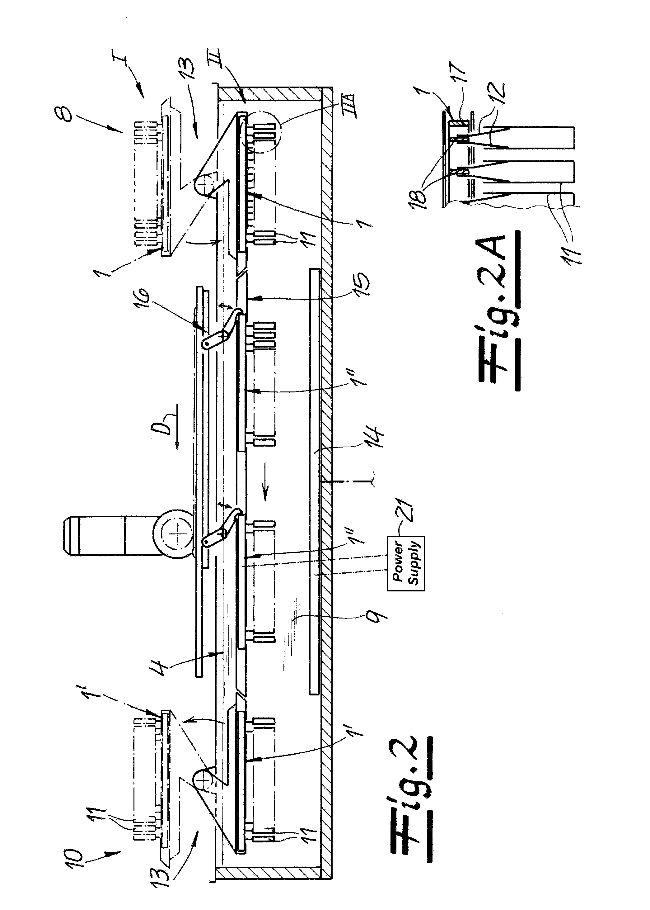
[0032]One of the treatment baths, for example, the anodizing bath 4 is schematically shown in FIG. 2. In a transfer station 8 of the treatment bath, the workpiece holders 1 are lowered into the treatment bath and are fed horizontally in a travel direction D in the body 9 of treatment liquid of the bath in one or a plurality of steps predefined by the work cycle to an unloading station 10 of the treatment bath. In a subs...


PUM

PropertyMeasurementUnit
Timeaaaaaaaaaa

Abstract

Cup-shaped workpieces are first each secured in a downwardly open position on respective fingers of a workpiece holder, and to holder is inverted such that the workpieces are open upward and the upwardly open workpieces are lowered into a body of anodizing liquid in a treatment bath until the workpieces are wholly immersed. The holder and the workpiece are then moved horizontally immersed in the body of anodizing liquid while passing electricity between the holder and a cathode immersed in the bath below the workpieces such that the liquid anodizes surfaces of the workpieces. Finally, the holder is raised out of the body of liquid with the workpieces open upward, and while the workpieces are still above the body of liquid, the holder and the workpieces are again inverted so that the workpieces are open downward and any treatment liquid in the workpieces drains downward back into the bath.

Description

FIELD OF THE INVENTION[0001]The present invention relates to a method of anodizing hollow metallic bodies. More particularly this invention concerns anodizing metal cup-shaped bodies.BACKGROUND OF THE INVENTION[0002]For anodizing, metallic hollow bodies or workpieces are secured on projecting fingers of electrically conductive workpiece holders, and the workpiece holders are transferred in steps in a predefined work cycle through a series of treatment baths including at least one anodizing bath in which anodic oxidation on the surfaces of the cup-shaped workpieces is effected by a closed electric circuit between the workpiece holder and a cathode in the treatment bath.[0003]Anodizing or anodic oxidation is an electrochemical process that converts the metal surface of a workpiece into a metal oxide. The resulting oxide layer is intimately bonded to the metallic base material. The layer thickness can be set in a defined manner by the selection of appropriate process parameters. Anodiz...

Claims


Application Information

Patent Timeline
IPC IPC(8): C25D7/04
CPCC25D7/04C25D11/02C25D11/005
Inventor BALAGUE, JOSEP VALLS
Owner THOMAS SA
Learn More