Low Energy Gasifier-Liquefier

US20140283547A1Inactive Publication Date: 2014-09-25KELLEY WILLIAM A

Image

  • Low Energy Gasifier-Liquefier
  • Low Energy Gasifier-Liquefier
  • Low Energy Gasifier-Liquefier

Examples


Embodiment Construction

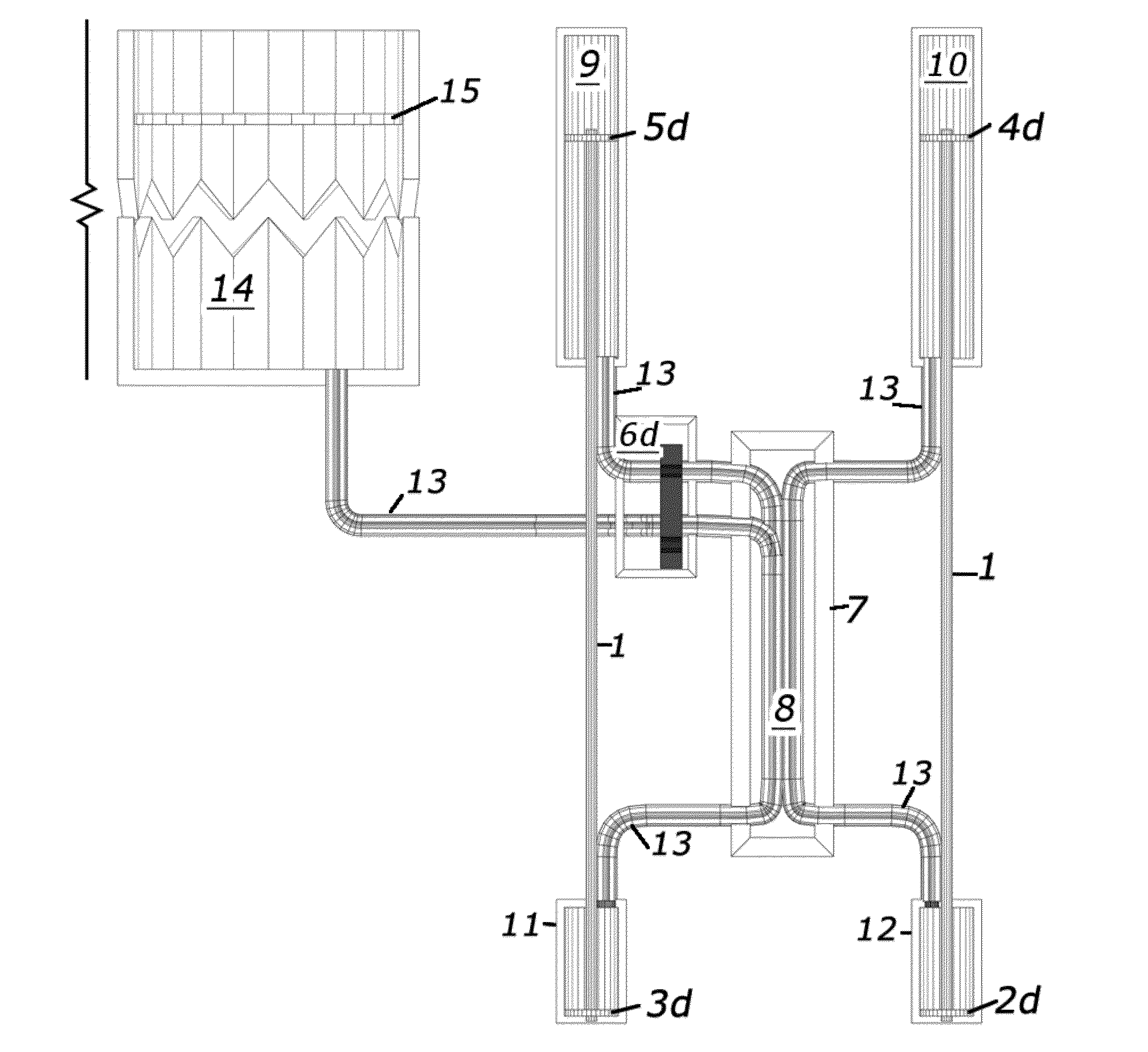
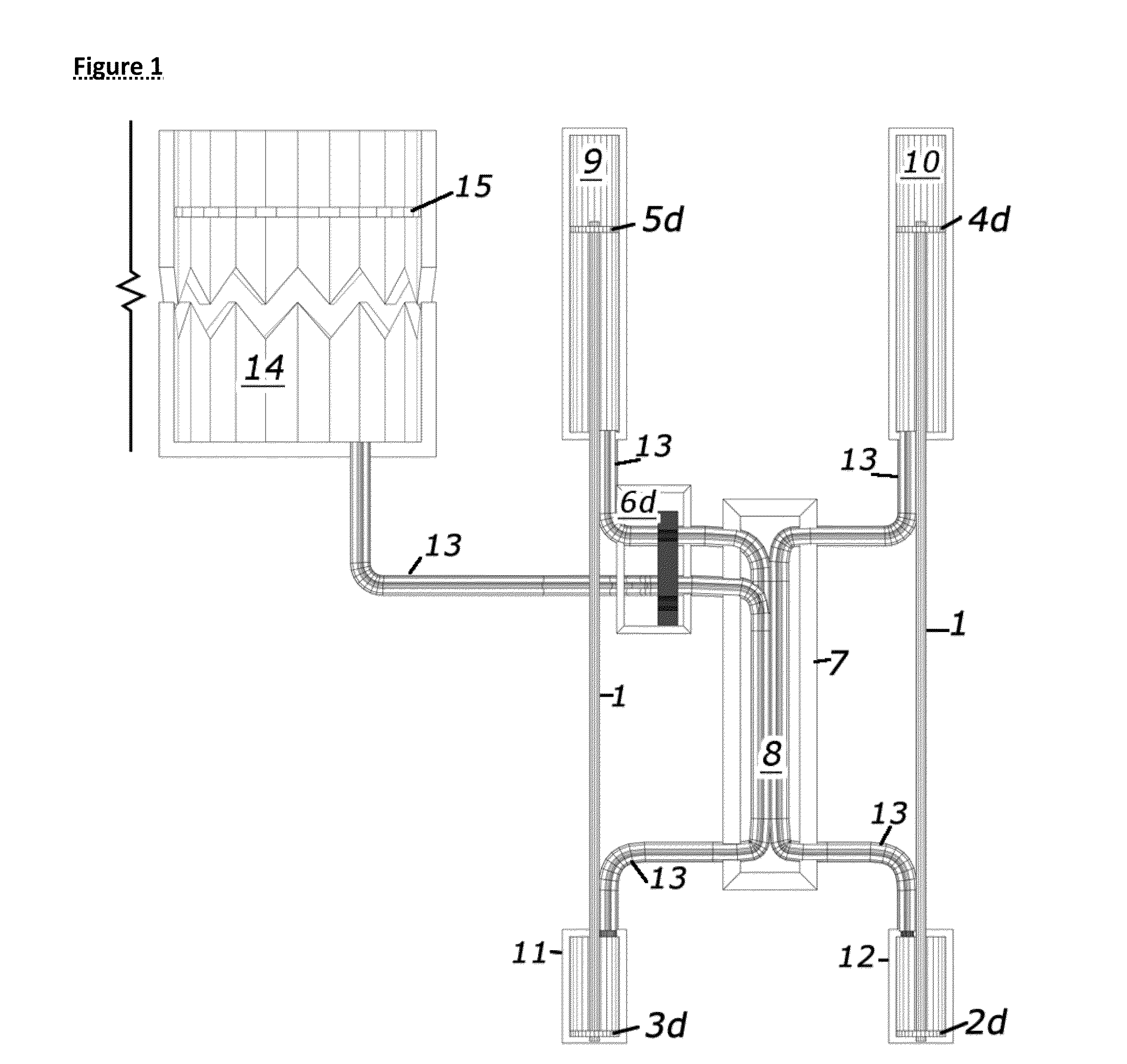
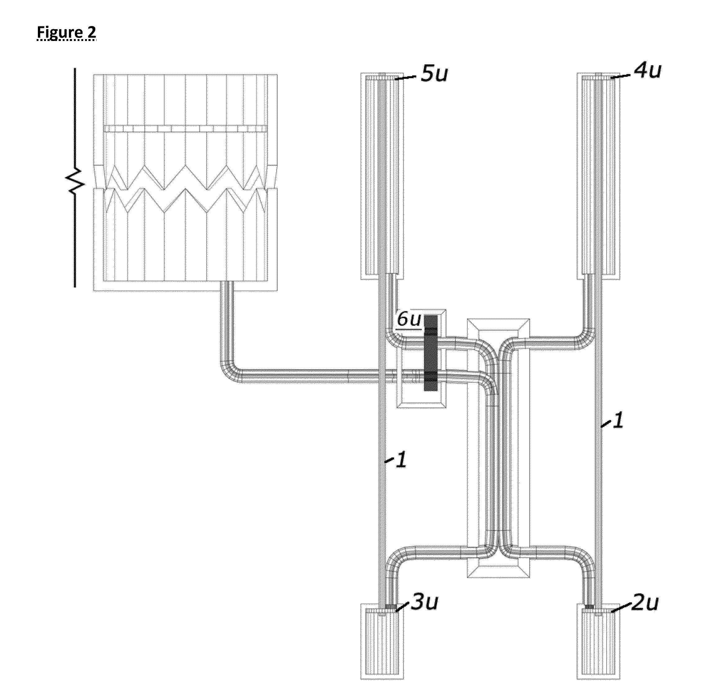
[0047]Both devices are based on a combination of counter flow heat exchangers (Patent A) and reservoirs of heat or cold. (Technically a cold reservoir is more accurately described as having less heat).

[0048]The fluids should be matched in thermal capacity. With the same type of material in both chambers, this simply means an equal mass of fluid. It would simplify the system to have a reservoir that remains in liquid state, if a material is available that is liquid over the required temperature range.

[0049]If liquid is to be cycled to gas and back to liquid, a hot fluid reservoir is required.

[0050]If a gas (vapor) is to be cycled to liquid and back to gas, a cold fluid reservoir is required.

[0051]In either case, optimal efficiency will be when the reservoir temperatures are just above or just below the boiling point.

[0052]The reservoir temperature is independent of the temperature of the fluid to have phase changed. It simply must have enough heat or cold capacity to supply or exhaus...


PUM

PropertyMeasurementUnit
Fractionaaaaaaaaaa
Temperatureaaaaaaaaaa
Pressureaaaaaaaaaa

Abstract

Disclosed are two related devices which can convert gas to and from liquid, or liquid to and from gas, with no expenditure of energy for heat of vaporization or for condensation. One device is designed for discrete units of fluid, the other for continuous flow. Both devices can be made fully enclosable. Both devices can compress an uncompressed vapor an arbitrary amount without additional energy. Applications include chemical separation, vapor compression, water purification, heat engines and power generation.

Description

CROSS -REFERENCE TO RELATED APPLICATIONS[0001]Related Patents have attorney docket numbers wakelley01, wakelley02, and wakelley03, wakelley04 and are listed below as Patent A, Patent B, Patent C and Patent D, respectively.STATEMENT REGARDING FEDERALLY SPONSORED RESEARCH AND DEVELOPMENT[0002]This patent is not federally sponsored.REFERENCE TO SEQUENCE LISTING, A TABLE, OR A COMPUTER PROGRAM LISTING COMPACT DISC APPENDIX[0003]Not applicable.BACKGROUND OF THE INVENTION[0004]Many processes require a fluid make a transition from gaseous state to liquid and back, or from liquid to gaseous state and back. These include chemical separation, compression, water purification, and power generation. This is an energy intensive process, as simple methods for boiling and condensing both take large amounts of energy. However, the initial state (temperature) and final state of the fluid's are generally the same, or can be. A mechanism capable of boiling a fluid, then saving the energy by boiling a s...

Claims


Application Information

Patent Timeline
25 Sep 2014
Publication
US20140283547A1
IPC
F25J1/00
CPC
F25J1/00; B01D1/0058; B01D3/007; B01D5/006; Y02B30/52
Inventors
KELLEY, WILLIAM A.